|
Modifying Old
Outboard Jet
Units to Flush Type
|
|
Non On The Water Test Running These Units : The OLDER units were not made with a flush adapter test unit. When I purchased my first outboard jet, I was a virgin, and totally uninformed of how these things operated, so when the seller slid a wheelbarrow up under the unit, filled it with water and started the motor, I thought this was standard procedure. he only ran it for less than a minute because he could not keep enough water pouring into the wheelbarrow because of all the LARGE flow being blown out the exhaust and out of the wheelbarrow.
Boy did I get enlightened, that was not the prescribed method. And not many old wooden cattle watering troughs still exist today.
A cousin of mine had this old Mercury jet on his sled and he kept complaining that every time he wanted to start it up before season, he had to make arrangements with a neighbor friend to use his river gravel bar to back the trailer/boat down into the river to be able to start it up for the season. I did a lot of information gathering, measuring distances on friends jet units and figured that if the factory devised a new method, that I could do a modification to these also. Therefore read the following, where I did tear-downs and a lot of head scratching.
Modifications to Older Non-Flushable Units : Many of these older units did not have the flush adapter plug hole and in order to run the motor, you had to back the trailer into a lake or river with the motor in the water enough to allow the water to be pumped up into the motor for cooling. This can be a PAIN IN THE KATOOSH, especially if you are those of us who like to run the motor the night before we head off at 0-Dark-30 the next morning. There is nothing I hate worse than getting to the launch, something does not work right while impatient boaters are giving you that unfriendly stare.
Flushing Conversions : Reading the manufacturer's information on their website says these units can not be converted. These units like many products on the market have undergone improvements as time went on and it appears this was one illustration. The big problem is illustrated in the photos below is that there is one main cavity for the older units, while in the newer ones the water pump cavity is separate from the exhaust cavity.
The manufacturer specifies "On jet drives in which the cooling pump is attached to the top of the bearing housing, it is not possible to provide a flushing inlet. Immersing the jet drive in a barrel of water doesn't work either, because the water is thrown out. Using a garbage can or wheelbarrow is not even an option as they will be emptied in about 16 seconds flat, sometimes even before you can turn the motor off. These units the impeller is turning all the time as it is tied directly to the driveshaft. The forward / reverse is accomplished by a clamshell on the outlet of the jet exhaust. Reverse (on the water) is supposed to be a happy combination of diverting part of the water forward. In reality you will have to play with the shifting lever to try to locate this position, not easily done!
Backing the boat into some fresh water was the solution.
"Present production provides a flushing inlet where it is possible to do so, depending on the model. If the parts book shows a flushing bolt and sealing washer, and your early jet drive does not have this, it can be added. Where to locate this threaded hole is called out on their engineering drawings. If in doubt contact the manufacturer." This is found in the operators manual.
These conversions can be installed on many of the older units by removing the unit, inspecting it to verifying just where to drill and tap the hole, or re-rout the bypass intake line. It may take a bit of thinking and understanding the functioning of the unit before this project is undertaken however. I have converted 2, one was a 1971 40hp Johnson and the other a 1968 50hp Mercury.
Both of these were the older A & E series smaller pumps and the modifications were slightly different on each.
We will cover the E series for the older 50 hp Mercury first.
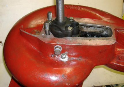
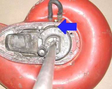
| Here is a "E" series drilled & tapped for a 1/8" street Ell, below this will be a 3/16" hole drilled in connecting to the threaded hole & thru the housing into the cavity under the water pump. | Here is the bearing housing installed into the pump housing to check alignment & location to drill the hole thru the body in line with the Ell. The arrow points to a 3/16" hole drilled below the fitting for water to be diverted into the cavity below the water pump. |
 |
 |
Above you will see a hardware store street Ell, this one was a casting and proved to be too long top to bottom by 1/8". What was found that worked just right off the shelf was a Weatherhead brand normally sold in an automotive type parts store. It was made from rectangular brass stock which was shorter both top to bottom and side to side. The one shown had to be shortened on the side to be the same dimension as the bearing housing so it could be inserted into the body from below, then it also being taller got bent on final assembly. I scrapped this one and found the Weatherhead brand did not need any alteration and fit perfectly.
On this pump housing just in front of where the Ell's top will be located is a part of the aluminum housing that may need to be relieved for clearance.
It takes careful measuring before drilling to be sure you don't screw up. Here I placed the Ell so it aligned between the 2 grease fittings on the side and drilled then into the side with a smaller hole so I could shift it if needed. It needed to be shifted, so I could insert a short brass 1/8" pipe in and thread into the Ell. Next after the pipe was tightened, I marked it, remove, it and calculated how much was going to be needed to allow for a nylon washer and just enough to align centered a 3/8" NC stainless nut to be silver soldered to the pipe. In the photo on the right below you will see the white nylon washer, the 3/8" nut, another washer & a 3/8" stainless bolt that has been cut off so that the threads will just stop inside the nut.
A 3/16" hole was drilled horizontally thru the bearing housing, connecting to the hole below the Ell's threads. Now I made a slightly tapered aluminum plug that was driven into this outer hole, being sure it stopped short of the Ells passage hole. Saw it off on the outside. then file to match the bearing housing. This hole diverts the water into the cavity below the water pump intake.
One thing we found is that since the fitting is for 1/8" pipe, that you may not get the water flow force out the pee hole that you normally would when the motor is running in the water. There is enough flow to cool the motor however since you would not run the motor at full RPM for flushing anyway. My cousin was worried so he tied a garbage bag over the jet unit, trying to retian more water for longer operation time. Well what-ever works was fine with him.
| Older E series converted to a flush unit, note that there is no divider between the water pump area & the exhaust area & the water pump is bolted directly to the bearing housing. Note - this old unit does not have the rubber grease coupler | L series showing a divider between the water pump & exhaust area, & the water pump is bolted above the bearing housing onto the pump housing, making it easier to get water into the water pump for flushing. |
|
|
 |
Modifications for the OMC or Johnson 40hp A Series Pumps : This unit is more compact in that the bearing body under the water pump impeller unit is a lot closer to the top of the jet unit body, so there is not enough room to put an Ell like on the Mercury conversion. Below is how I did the OMC conversion which is a lot easier than the Mercury. I had never seen a conversion done before, so am not sure how others do it, but this one works.
Locate a position near the center of the bearing housing on the left side above the grease fittings. Measure down about .650" (on the one I did it was .750" but that puts the hole just a little bit too close to the grease fitting hoses). There appears to be enough metal in the bearing housing to raise it the .100". Line the drill as square as you can and drill a 5/16" hole thru the jet body. Go thru enough so that you touch the bearing housing enough to mark your location. Remove the bearing housing and shaft unit.
Tap this hole in the jet housing to 3/8" X 16 NC threads.
Using the marked location, drill a 1/4" hole clear thru the bearing housing and into the cavity under the water pump impeller lower plate. Now with a 3/8" drill, spot countersink the outer hole you just drilled in the bearing housing. What you are now trying to do is to make a mating Vee surface that will block any water from escaping when you insert the plug screw, then later the flush adapter.
The reason for this, is if you notice there is a 3/16" plus gap between the bearing housing and the jet housing. In operation, this is filled with exhaust gas and water. It needs to be separated from from the inner suction water. So now the plug screw AND the flush adapter needs to be just long enough to go thru the jet housing and bottom out into the Vee you have drilled in the bearing housing.
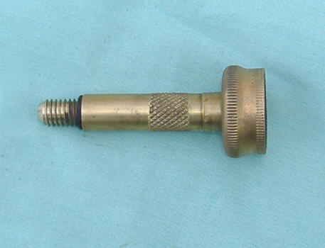
In the photo below my adapter threads are longer than the commercially obtained adapter and there as a O-Ring at the shoulder. This is to that If I did not get the dimensions exactly right on the threaded and tapered end that the rubber O-Ring would compensate some of the take-up. The overall length of my threaded end from the shoulder to the end is 5/8". This could vary on how deep you countersunk the bearing housing however. The center water hole in the adapter is 3/16". I just used an old garden hose female end and lathe turned a brass shaft. Match the taper of the 3/8" drill to the taper you make the plug and adapter tapered end. The shaft is held into the threaded garden hose end by the rubber garden hose washer.
The plug screw will be made to the same dimensions & use the O-Ring as the adapter.
| Notice the longer threads & the taper on the threaded end |
 |
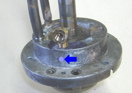
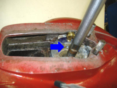
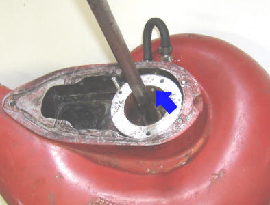
In the left photo below, you can just see the inner threads of the plug screw at the point of the arrow. In the right photo again at the arrow is the inner hole into the water pump suction chamber below the impeller plate.
In final assembly you need to install the stainless steel water pump impeller plate on top of this aluminum bearing housing and the water pump then bolted down on top using the 3 threaded bolt holes shown in the photos. Place this impeller plate so you can see the shiny wear of the impeller up. It can only go one way after you have the wear up because there are 3 unevenly spaced screws that will only go one way.
| Plug screw & inner threads shown | Inner hole into the water intake chamber |
 |
 |
Alternate A Series OMC Method :
Another method would be similar to the Mercury conversion shown above except no Ell.
Using the same location, drill into the bearing housing and tap it for 1/8" pipe,
then open up the jet outer housing so the pipe would be a slide fit and yet thread
into the bearing housing. Cut the pipe and silver solder a 3/8"
stainless nut onto the pipe allowing for a nylon sealing washer under the nut.
Then you can use the factory hose flush unit. This method lets your unit
that stays on the motor protrude
the thickness of the nut farther out.
A suggestion on this A series jet units is that when you are reassembling the foot, replace the 1/4" stainless steel Philips head screws with stainless steel 1/4" Allen head screws. If the Philips heads get worn, your only hope to remove the foot is to hacksaw the heads off for the foot removal. At least with the Allen head the wrench will not be forced out in the confined space you have to work in. If the motor has sat for a while and you happen to be the chosen one to work on it, these bolts may well be frozen.
Also for these older units, they use a stainless steel round pin of about 3/16" diameter to keep the impeller from rotating, plus an eared washer under the shims to keep the pin in place. They also use a stainless steel cotter pin to hold the impeller nut in place.
Copyright © 2007 - 2026 LeeRoy Wisner All Rights Reserved
Back to the Main Ramblings Page
Originally started 02-03-2007, Last Updated 02-06-2026
Contact the author