22 RF Revolver Repairs
|
|
High Standard Standard 22 RF Revolver Repairs |
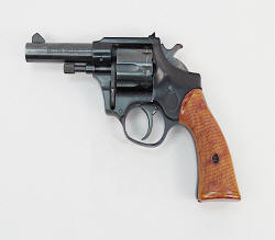
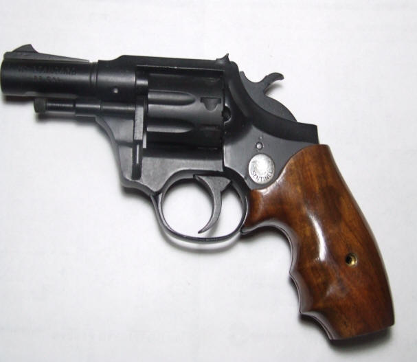
Models ; These models were made in various versions: The western versions, being Double Nine, Durango, Hombre, Posse, and Longhorn. There were a few shorter run versions of this series, usually with shorter barrels.
The Sentinel, Sentinel Deluxe, Sentinel Mark1 and
Mark IV were more conventional regular type revolvers. The Mark1s had fixed
sights, while the Mark IV had adjustable sights. The Mark series also had a
under-lug barrel and a
steel frame, as compared to all the others which had aluminum frames.
The model numbers are collated to the type -- (from my
observation) meaning the W
series were Western Style, while the R series were the Regular police type. And
many could have been had in either blue or nickel finish.
One note of interest might be since this cylinder has 9 chambers,
the amount of rotation to align the next shot is less than if it was a 6 shot as
in a 357 magnum. Therefore there is considerably less movement of the
hand. Which relates to less pressure needed on the trigger when in a
double action mode.
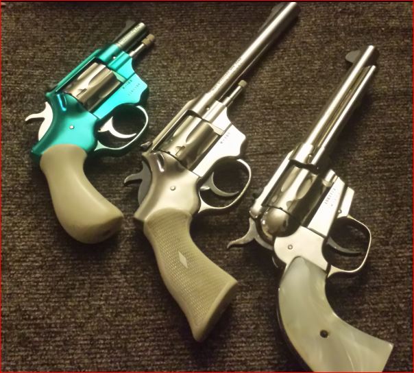
| Here you see a glimps of the different models that were offered |
 |
These pistols were made from 1955 (and sold
for a price of $37.50) up until
the 1976 with numerous variations, like barrel length and grips. Many of the internal parts were
interchangeable. All these revolvers were 9 shot and made in 22 LR, but with the Mark IV pistols in 22 WMR.
A few versions could be had with dual interchangeable cylinders. And extra
cylinders could have been had through the parts department, thereby add to existing
guns by the owners, or gunsmiths.
These guns were originally put on the drawing board as a
request from Sears Roebuck (who just happened to be a part owner of High
Standard at that time). They were the brainchild of Harry Sefried, who had
previously worked for Winchester on military firearm improvements, then after his employment with High Standard
he went to work for Ruger designing numerous guns for them, of which he retired
from in mid 1980s. He suffered for 25 years of Renal Cell Cancer, passing
a way in 2005.
R-100 was introduced in 1955.
(no spring extractor in cylinder)
R-101 was introduced in 1956. (no spring extractor in
cylinder) but a newer hammer pivot bushing
R-102 was introduced in 1961,
with addition of self retracting extractor and 3" barrels were dropped
R-103 was introduced in 1962 the
cylinder ratchet cuts were changed
R-104 was introduced in 1961, was a economical target gun, different hammer, trigger and adjustable sights.
R-105 was introduced in 1963,
when Sears & Roebuck dropped the handgun line, so HS modifded existing
inventory, replaced barrels and grips, rebranded them off the slightly different
Sears frame
configuration
R-106 & 107
R-108 was introduced in 1967 with shorter barrel and 2 piece
grips
R-109 was introduced in 1969 being the "Kit Gun"
MK 1 & MK IV was introduced in
1974
All manufacturing of these handguns ceased in late 1976
Sears version of the Sentinel was their
model 88, while Western Auto's Revelation model was the 99
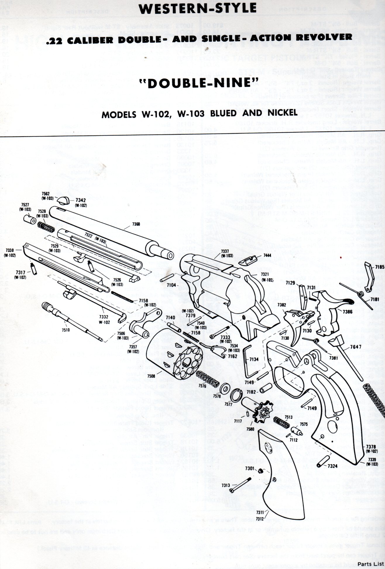
The Western style revolvers model numbers begin with the W-100 design series and
continue through the W-106 design series. The changes of design series
designations indicate design changes to the guns. They were
introduced in 1958.
To simplify production, it appears that the major internal
parts, and the cylinder are sintered metal
(powdered metal, highly heated, then pressed into a mold), making a precise part
with little machining needed.
Disassembly ; The first thing to do is to remove the cylinder. Here is a rewrite from the factory instructions --- "Swing the cylinder assembly out to the open position. Depress link pin with a 3/32" diameter or small drift punch. With the pin in the depressed position, gradually pull the crane and cylinder from the slot in the frame until it binds on the drift pin. Remove the drift pin and place your finger over the link pivot pin hole on the frame. Now pull the cylinder assembly completely out of the frame. Your finger will prevent the spring and link pivot pin from flying out and becoming lost".
Next remove the grips.
Then with the same punch used to remove the cylinder, tap out the hammer retainer pin which is about 3/4" behind the rear
of the cylinder opening in the frame, and slightly above the same bottom of this
opening. Either direction is Okay. On newer models you may see
a second retainer pin forward of the cylinder on the lower grip frame. However, depending on the model,
you may want to be careful as on the early models the hammer will then be under
the hammer mainspring tension. The later models used a hollow
bushing here that retained the hammer unit on removal and reinstall.
All the models except the Mark series used a integral hammer mounted firing pin,
while the Marks used a separate frame mounted spring returned firing pin.
The most common issue you will encounter is that the cylinder
stop will not engage it's notch in the cylinder, which will allow the cylinder
to slightly over rotate, possibly causing a misfire if it goes to far. Or
the firing pin will strike the
cylinder slightly off center causing damage to the firing pin, but not the
cylinder because of it's hardness.
This issue can usually be attributed to the cylinder stop may have become gummed up
inside the grip frame AND OR its return spring is slightly bent, or has also gathered debris, not
allowing the stop to raise sufficiently when the trigger trips it to engage in the cylinder notch
at the proper time.
If the cylinder does not rotate it will probably be a broken hand spring.
If the trigger does not return, it could be due to a weak or broken trigger return spring, otherwise you would normally not need to remove the trigger from the grip assembly during a normal cleaning.
|
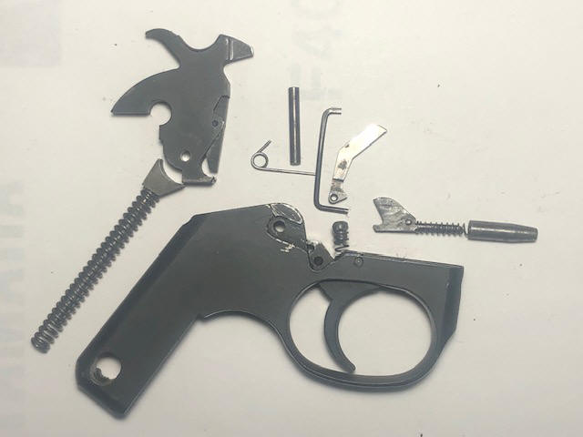
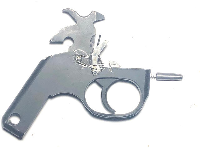
Here you see the inner grip-frame components laid out in close proximity to their relationship grip-frame/trigger guard for a model R100 |
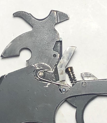
Here you see a closeup |
 |
 |
Reassembly ;
Now comes the fun part.
Reassembly
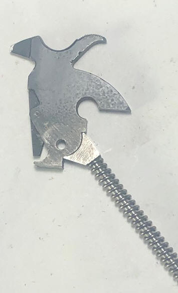
would start with installing the hammer. Here the position of the hammer spring guide (#7645) is critical to
be able to force the firing pin to retract slightly from
full forward contact with the
cartridge rim (rebound) after firing to facilitate cylinder
rotation. In observing factory illustrations, this is
contradicted in different illustrations. The cup
socket of this guide is not concentric or ears equal in length, the proper position
is that the upper flat (rear) needs to be parallel to the
spring guide's tail (as seen in the photo above).
I have found that it is a lot easier if the trigger
has been removed (less constriction) when needing 3 hands to
compress the hammer in the spring plunger cup all inside the
inner grip frame (technically my terminology is wrong as the
factory calls it the #7923
trigger guard) AND install the retainer pin (while under tension)
all at the same time. This is usually
easier to do it from the LH side so you can see and to maintain
the hammer spring guide's lower tail and spring being held rearward to
allow the tail to enter it's mating hole in the grip frame
bottom rear during the compression procedure. It is
also easier to ensure that the guide tail/spring a more easy
to align and fit into it's hole (with the trigger out)
to angle it forward in the hammer slot, forcing the tail
into the rear corner and hole at the rear of the grip frame.
Here you will have to make a "Slave Pin" 1/8" dia. by .440", or
just slightly narrower than the grip frame. This
can have one end slightly chamfered to help facilitate
installation pushing out the temporary retainer punch pin.
Tap the punch back into the hole (back into and), and just
enough to allow the slave pin (with a slightly chamfered one
end) to facilitate starting it in this pivot hole. You may
have to put upward pressure on the punch to help align the
hole enough to be able to tap the slave pin in, pushing out
the punch. Now you have the hammer assembly in stalled
in the grip frame, where when completed, you can test
function before inserting this trigger guard into the frame.
Once aligned, you can captivate these by inserting a 3/32" or slightly larger punch into the 1/8" hole in the frame and hammer. Then pull the drift punch back out enough to start the slave pin. Once it is in one side far enough , tap it more, driving out the punch, as seen in the photos below.
With the hammer in this grip frame housing, you can now install the trigger. But you have to time it (mesh) to the hammer, pulling the hammer spur back enough to allow the protruding rear part of the trigger (it's tail that engages the spring loaded hammer strut) (technically the pawl) which allows the hammer to be cocked by the trigger in double action mode. Depending on the model (newer more common) the trigger spring needs to be installed prior to this assembly.
Now install the cylinder stop (#7162) and it's spring (#7158)
(note the it's tail-rod is bent offset). With the
spring on slide the spring into the cylinder pivot hole from
the inside, then pull/push the stop rearward and down so
that it's two ear pins engage under the trigger's ears.
Next would be to install the hammer safety bar (#7134)
into it's hole on the LH side of the trigger (low and rear),
push the long tail`` all the way through until tight against the trigger.
Now on the RH side install the hand (#7574) onto the
protruding end of this bar. (This is not really a bar but a
small round
bent rod).
Now comes the hand spring (#7181) this is a
simple wire with one coil and two tails, a long and short
(like a safety pin). It is inserted with the eye end going over the RH end of
the slave pin. The short end will be up and and under
the upper depression of the grip frame as seen in the photo
below. The longer tail pulled up and into the
side groove in the RH side of the hand. NOW maybe
we had back up to before you did anything, and that is to
use a SMALL round file or a Dremel tool cutoff stone and cut a
slight undercut where the short tail will be slightly
captivated in the grip frame when it is inserted. (This
facilitates holding the spring in place (as seen in the
photo below) as you try to later
to insert the trigger guard assembly into the frame as
described below).
| Here you see the relationship of the hand and it's spring, along with the top of the old syle trigger spring & plunger just forward of it, then the cylinder stop on the far right |
 |
As seen in the photos below, you can now assemble both halves, with
the cylinder stop AND spring off it's shaft, slide the grip frame
up angled into the main frame, with the hammer going in
first.
Be sure that the safety bar is rearward so it slide up into the main
upper frame. Now raise the rear of the grip frame into the upper frame,
all the while being sure that the hand spring maintains it's
position. When the lower and upper frames are in place,
then align and drive the hammer pivot pin into the upper frames hole,
driving out the slave pin. Now you can slide the
cylinder stop spring into the pivot hole and over the tail
of the cylinder stop. If you leave it on and try to
tuck it up under as you slide the two together you will
likely bend this spring.
The front of these
frames are secured by the cylinder pivot plunger pin when when installing the cylinder.
On some succeeding models there may be a second pin through
the frames in front of, and below the cylinder.
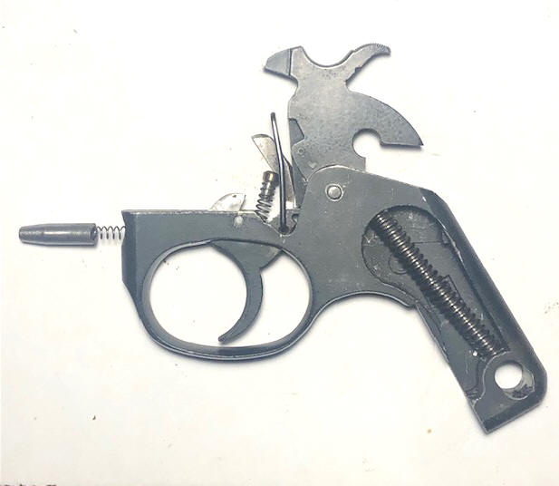
| Here you see the RH side of the grip-frame components installed in a model R100 | Here you see the LH side of the grip-frame components installed in a model R100 |
 |
 |
As a note, the Sentinel shown here is the R-100, (1st and only year of production). The later versions 1956 (R-101) had two changes. And these carried through on all later models/versions. The hammer pivot now has a sleeve or hollow bushing as a hammer pivot which makes for a lot easier pre test and final assembly (no slave pin and not under pressure). And they eliminated the coil spring trigger spring and plunger, replacing it with a wire Vee type pinned in place one on the rear of the trigger.
It is STRONGLY recommended to DO NOT try to disassemble the cylinder assy. If it needs to be cleaned, try to flush it with WD-40 and use compressed air, OR an ultrasonic cleaner.
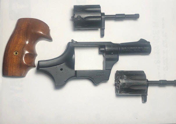
| Here you see the main frame, dual cylinders oa a restored R-100 model |
 |
|
Here you see the finished pistol with a custom grip
installed on 3" barreled restored R-100 model |
 |
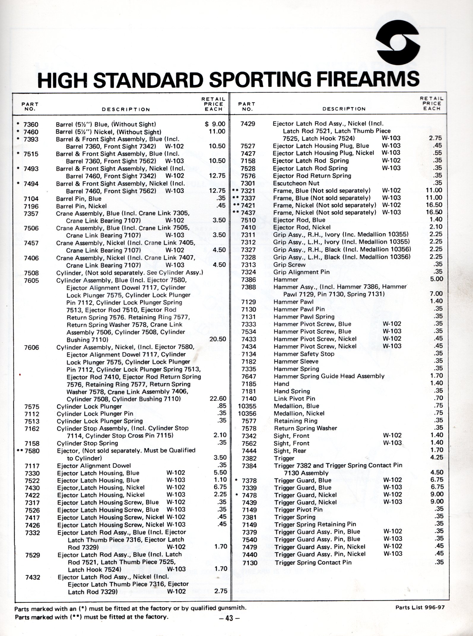
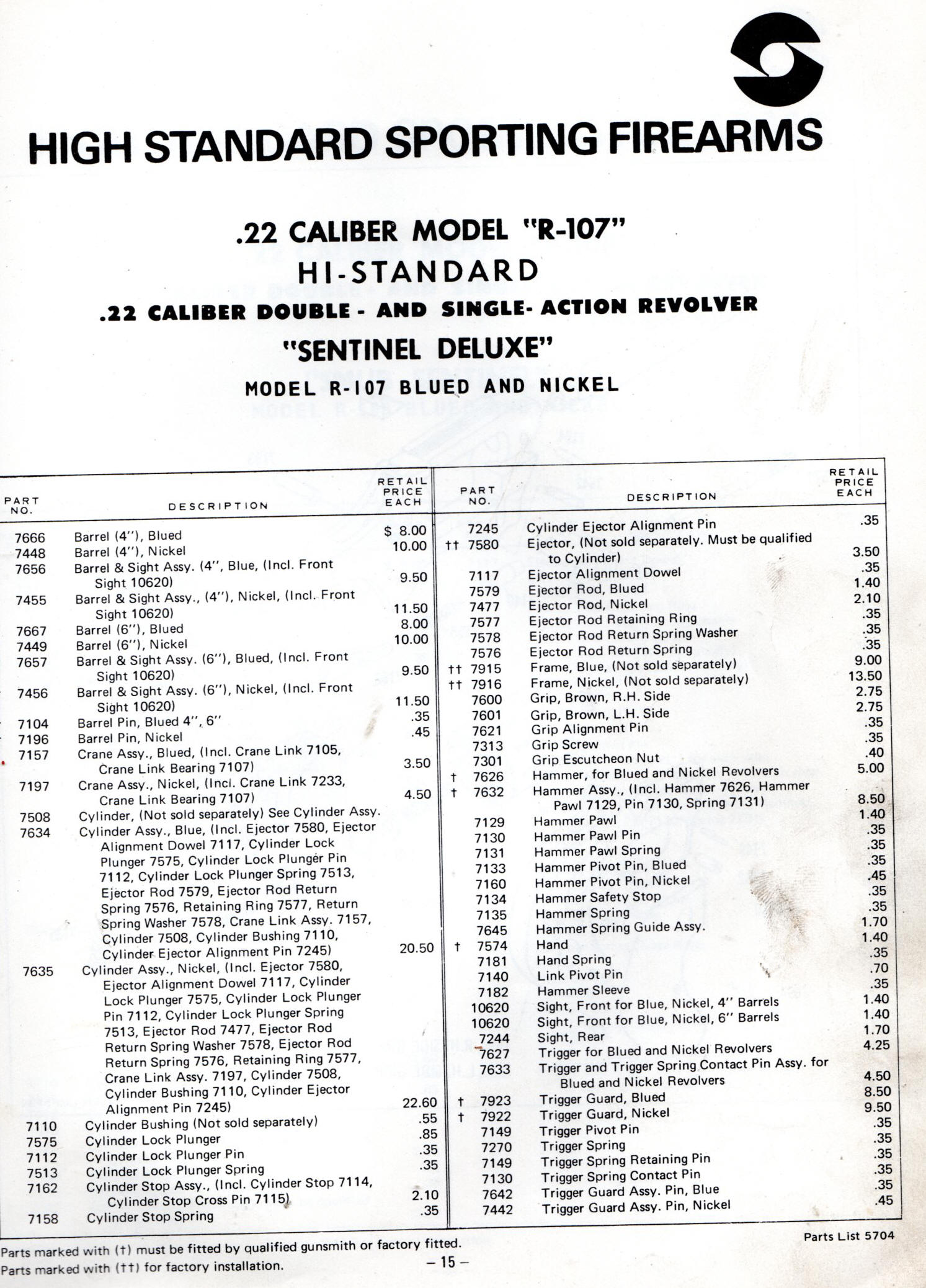
The images shown below were taken off a 1980 High Standard
parts and accessories list.
This is not a comprehensive list of all the models made, but a
reprehensive illustration.
Again MANY of the INTERNAL parts could interchange.
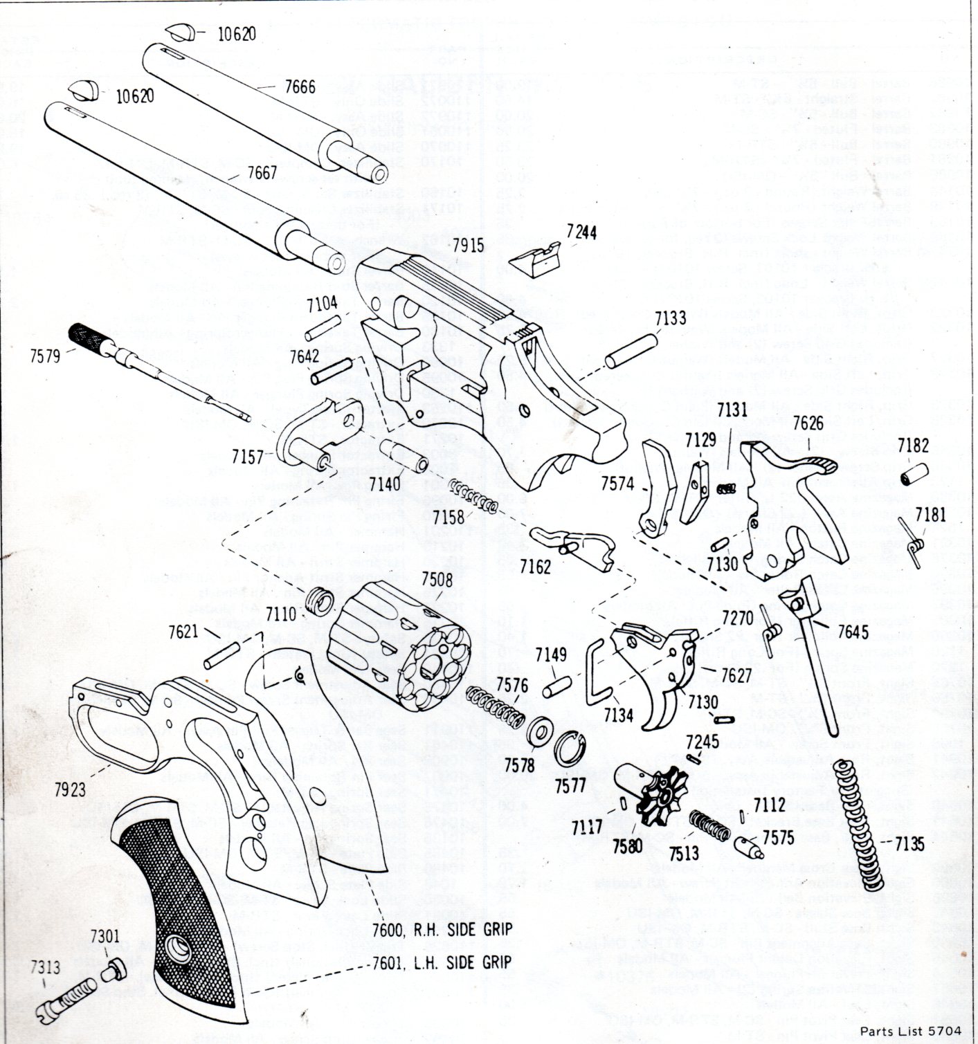
Regular Style 22LR Revolvers
Model R-107
7162
Most all articles here are Copyrighted from 2025 - 2026 by LeeRoy Wisner
Back to the Main Ramblings Page
Originated 12-29-2025 Last Updated 01-08-2026
Contact the Author