 |
Maintaining Johnson/Evinrude 1965 – 1979 (General Repairs) |
|
JohnsonJohnson, Evinrude, OMC, outboard motor, outboard motor repair, outboard troubleshooting, 6 hp, water pump, carburetor,
 |
Maintaining Johnson/Evinrude 1965 – 1979 (General Repairs) |
|
One thing that I want to convey here is that I write only on motors that I have actually worked on, and over a period of MANY years, consisting of many THOUSANDS of hours, and then many more in maintaining/updating these articles. They are motor specific, HOWEVER if you are having a diagnosis issue, my Trouble Shooting article covers MANY more aspects that may help you diagnose your issue. CLICK HERE for access to that article.
What I have found is that most of these little motors 10 hp and under usually have lived a hard life. The majority are used occasionally, but run hard by a non-motor oriented person, hauled in the back of a pickup truck bed, then thrown in a shed or barn corner until next time. As an old horse trading days saying goes, "Run hard and put away wet".
A few years ago I was in a Johnson / Evinrude marine shop waiting on the parts guy to finish his transaction with another customer, I could not help but wondering around thru their racks of used motors for sale. I noticed, of the motors here, there were about (5) Evinrude 6hp Fisherman and possibly (8 or 10) 9.9/15hp Johnsons making up about 1/2 of all motors from 2hp up to about 30hp that were there. So, from what I saw there, it appears there were a lot of the older OMC smaller motors still around and being sold.
It appears the first OMC 6 hp were introduced in 1965, Johnson model was CD, while the Evinrude code was from 6200 to 6900. Prior to that this, the same basic motor existed as a 5.5 hp, so what you see for the 6hp, here may also pretty well relate to the earlier 5.5hp motors. And then after the 5.5s were dropped a 5hp ran parallel with these 6hp motors for a while.
These early 6 hp motors are relatively simple to work on, in the fact that about anyone with a little bit of mechanical ability can work on them and keep them running. Those who shy away from the older points and condenser ignition system because they think they are obsolete and they don't run very good, should try one of these when it is set up right. After I have finished rebuilding the one in this article, it only takes one pull or two to start it no matter whether it is hot or cold and it is seeing many hours trolling on my grandson's 16' Hewescraft boat.
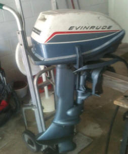
Here I will mostly be dealing with a 1972 version Evinrude Fisherman. It seems that every used motor that I have ever bought from a private party has had something wrong with it. Many times I purchased it from a person who never even ran it and had gotten it from someone else. The problem is most of these people were considered friends (prior to the motor deal). No matter who or what the circumstances, I seem to have to do repairs, AND with some of them having gotten extensive. It appears that most fishermen do not know how to maintain their motors, or maybe even do not care, as long as it runs somewhat.
But I refuse to travel to a fishing area with a motor of an unknown quality, taking the chance of a potential problem. Any used motor I repair has to run in a tank for a few hours at all speeds before I am convinced of their water cooling condition and carburetor idle jet setting. I often times even start then up the night before a fishing trip if they have sat for a while, to be sure they will be running when I am ready. I am getting too old to have to crank and crank on a cantankerous motor or have to resort to a paddle to get back to the launch or worse just to a shore. I have even called a couple of fishing trips short by a day or so because of a motor that did not appear to be running right. I have also struck out a couple of times and had motor failures on the water.
This motor being worked on here was ultimately given, along with a 1968 10' Columbia fiberglass tri-hull boat to my 19 year old grandson.
Year of Manufacture :
This is important in any repair, for obvious reasons. For Johnson,
the
1965-1968 were designated CD models. Evinrudes model code uses the first
number as the HP, second year and third/forth the version, where usually, say as
illustrated below 6602 being a 6hp, 1966 year, then a short shaft, where
the 6603 would be a long shaft. They were made in standard 15" shafts or
the long 20" versions where Johnson designated by a 3rd letter L in the
model number. However finding a longshaft motor of this series is quite
rare as in those days most of these small motors were used on small fishing
boats and not as kicker motors for larger fishing boats.
Johnson
Evinrude
CD / CDL 22
6502 / 6503 = 1965
CD / CDL 23
6602 / 6603 = 1966
CD / CDL 24
6604 / 6605 = 1967
CD / CDL 25
6802 / 6803 = 1968
6R-69 / 6RL-69 6904 / 6905 = 1969
6R-70 / 6RL-70 6002 / 6003 = 1970
6R-71 / 6RL-71
6102 / 6103
= 1971
6R-72 / 6RL-72 6202 / 6203 = 1972
6R-73
/ 6RL-73 6302 / 6303 = 1973
6R-74
/ 6RL-74 6402 / 6403 = 1974
6R-75
/ 6RL-75 6504 / 6505 = 1975
6R-76
/ 6RL-76 6604 / 6605 = 1976
6R-77 / 6RL-77
6704 / 6705 = 1977
6R-78
/ 6RL-78 6804 / 6805 = 1978
6R-79
/ 6RL-79
6904 / 6905 = 1979
For Johnson, after 1968 the year was incorporated in the model number as explained below.
6R69 / 6RL69 = 1969 as seen above.
As a model
6R78SC,
would indicate a 6 hp,
Rope
starter,
1978
year of manufacture and C
model revision. Since this does not have in the code L
between the hp designation and the year, it is a short shaft version.
The numbers you are looking for will be the first 3 numbers which equates
to the hp and then the middle to the year, as 6
hp,
the (4)
equates to
1978
where the (S
)would indicate a shorts shaft.
Here is a
LINK
to
help you determine any of the Johnsons. And here is the
LINK for the Evinrudes.
Evinrude
in those years used a different 5 digit model code, as 6902.
For those of you readers outside of the United
States, here is another
LINK
that may better help with your motors.
After 1979, OMC's manufacturing year code, which included Evinrude, is the word "INTRODUCES", with each letter equating to a number ie: I=1, N=2, T=3, R=4, etc. as illustrated below. As before, the last 3 letters are what you are looking for. Then in this case, disregard the last one, as it pertains only to a model revision that only on specific cases may be revalent to a marine repairman if problems arise. A code of J10ELENA would equate to Johnson, 10hp, Electric start, Long 20" shaft, EN = 1992, & the A could be a model revision, so this motor would probably be made in the very first part of the year. You may encounter a code of something similar to J10SELCTC. This would have been Johnson, 10hp, SailMaster, Electric start, Extra Long shaft, 1983, and the C could be a model revision. In this case with the SE in the model number, indicating a SailMaster, all the SailMasters would have all had the extra long 25" shaft. For more detailed information on worldwide production, CLICK HERE
|
CODE |
I |
N |
T |
R |
O |
D |
U |
C |
E |
S |
|
|
1 |
2 |
3 |
4 |
5 |
6 |
7 |
8 |
9 |
0 |
Using
this code system, if the motor was sold as an Evinrude, then the first letter would have
been an E
instead of the J
for Johnson.
Then you can encounter motors made in or for other countries, which will have
some added letters as mentioned later in this article.
Usually the name / ID plate will be found on the LH side (looking
forward) of the
upper steering/clamping bracket. Sometimes however it can get removed. If this happens, you can
still usually tell which motor it is by looking at the 25 cent size soft plug in the
upper rear RH side of the block. This will usually have the actual OMC
model and the serial number, OR a code that usually an uncipherable code except by the factory. It is interesting to also note that the
6 hp uses the same
block as 5hp and the 8hp, so you could see either hp with the same 6R78M numbers here as
the 8hp
has. You may find that the plug numbers
do not match any of the codes, as the factory changed things as time went on.
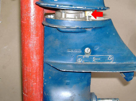
Shown in the photo below, you can see the model is a 6202 series D. This "D" represents a slight model change, so obviously would not have been made very early in the year. Now by going to my Evinrude ID article http://www.leeroysramblings.com/evinrude_1913-1979.htm and looking up the model 6202 you will see it was made in 1972.
Again in the photo below, where here the serial number is preceded by a J, my guess here is that that both the Johnson and Evinrude came off the same assembly line, but the Evinrude split off with a different paint job and cowling.
| The soft plug ID of a 1972 6hp Evinrude |
|
|
Statistics For These Motors :
These motors
develop 6 hp @ 4500 RPM
Cylinders
2
Bore diameter
1.940"
Stroke
1.500"
Displacement 8.84 CI
Starter
automatic rewind
Bearings,
bronze bushings for all mains and needle rollers for the rods
Carburetor
OMC, metal float type
High speed jet, Preset
Idle jet -
3/4 turn out
Fuel capacity - remote tank
Fuel/Oil mix is (50
:1)
Ignition -Magneto Point
gap is .020" (pre 1977)
Ignition - Electronic
(post 1977)
Plug gap
.035", Champion J6C or J8C spark plug.
Flywheel key - Woodruff .153" wide
x .235" thick x .603" long
Flywheel nut - 3/4" wrench
Water Cooled - Rotary vane water pump
Gearbox oil - 90
W gear oil
Gear
Ratio -
15-26
Prop. dia. & pitch- - 2 Blade 8" X 7 1/4"
Blade, or 3 blade 8 1/2" X 5" with 9/16" bore
Shear Pin - 3/16"
diameter X 1.380" OAL
Prop nut retainer pin - 3/32" X 1"
Prop nut - special nut, 1/2" X 20
TPI NF
Paint Color
Weight
Exploded Parts
Lists :
For a
internet link to a marine parts seller
CLICK HERE
that has exploded views as shown below in this article. From
this business, you can identify the numbered parts and purchase parts
online from them.
Cowling Change : There was also a cowling change in1976 where the aluminum lower cowling had a straight upper edge with a matching straight lower edge on the fiberglass cowling. The pre 76 cowlings are not interchangeable with the later ones. This coincides with adding electronic ignition, and a starter interlock.
Similarities : In this series of motors, I am not as familiar with all the variations as I am with the 9.9/15s (but learning), but have been fortunate enough to have a reader from Australia who has supplied some data that I was not aware of. My thanks go to Noel Puzey.
"There are many similarities between the 5, 5.5, 6 and 7.5 hp motors of the years up to near the 1972 being written about here. The lower crankshaft seal unit is the same (with slight variation of how it is retained) for most of these. Water pump impellers are the same for all from 2hp to the 7.5hp in years 1952 to 1978. The 1979 impeller was an odd ball using a smaller diameter. Some motors close in HP range used similar carburetors (either jetting or throat diameter being different), reed valves and intake manifold may have been changed also. Many even shared the same sized pistons, while others may have had a larger piston while sharing many other common parts but a different carburetor. Smart thinking by the manufacturer."
In this small series of motors you will find the 5hp Evinrude made from 1965 to 1968 both used the same Evinrude powerhead and lower pan as the 6hp, with the upper cowling generally the same, but used different latches. The Johnson LD series was the same except the more squared motor cowling. The recommended spark plugs for these motors were Champion J4J. The main difference on these 5hp was that the carburetor on the 6hp used a different mainjet to which allowed 500 RPM over the 5hp. And the 5hp had no shifting gearbox along with a less refined transom tilt system.
Then a 4hp followed, using a Johnson model of 4R70E. This one used a totally vertically different pivoting spool type starter and the throttle lever is simpler, being a rod on the RH side. These would have had the electronic ignition however. It also used the remote fuel tank as the 5hp and 6hp, while other motors in smaller size utilized smaller internal tanks. Probably the same lower unit/gearbox was used on both. And it appears that no thermostat was used on this one. And it could be purchased in either the standard horizontal gearbox or the angled "Weedless" unit.
Some of the following parts are shared by other size motors, the gasket OEM # 329103 fits 5 hp 1965-1968, 5.5 hp1959-1964, and 6 hp 1965-1979. Gearcase seal kit 6 hp 1968-1979
Internal Engine Parts : This engine has a bore and stroke of 1.9375 ' x 1.500" and the ring width of.0935", with a displacement of 8.8 Cubic Inches. Both the center main bearing and the connecting rod bearings are non-caged needle bearings riding in a stainless steel liner. These bearings are not interchangeable as the center main bearing is larger than the rod bearings. The motors up to 1976 used points and condensers, with the points set at .020".
In 1977 the ignition was changed from points and condensers to the electronic ignition, Capacitor Discharge Ignition, (CDI) using a power pack with external coils like the 9.9/15hp used of the same era. The later motors also started using more plastic parts than previously seen.
Flywheel : To get to the magneto (which consists of the points and coils) which are under the flywheel, you will need to pull the flywheel off the tapered shaft of the crankshaft. Removal of this nut needs a 3/4" socket. If it is so tight that you can not loosen it normally, then try to tap the wrench with a medium hammer to jar the nut loose initially. If that does not work then you will have to resort to a strap wrench or a air impact gun.
Most times if you just loosen the flywheel nut a few threads, (leaving it about even with the shaft end) then hold onto the flywheel by wrapping your arm around it and lift up enough to put a lot of strain on (almost holding the motor upright) then rap the nut HARD with a HEAVY brass mallet, the flywheel should pop off the crankshaft spline. The reason for the brass hammer is so it does not damage the nut or shaft threads. You could get by with a regular hammer if you are careful. One hard rap is better than a dozen love taps.
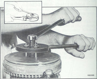
If this does not pop the flywheel loose, then you will have to resort to a flywheel puller as shown in use below. These motors have a thin aluminum cover held in by the flywheel nut that covers these puller holes. There are 3 holes that are threaded 1/4" X 20 TPI. The pullers usually have 3 slots milled in the top flange to accommodate the bolts to be threaded into corresponding threaded holes in the top of the flywheel. This puller could be also use if only 2 opposing holes were there. The large bolt in top is threaded into the puller boss. In use, you thread the 3 smaller bolts into the flywheel so that they will allow the puller to set evenly on top. You then tighten the large bolt into the puller, which puts pressure on the crankshaft end, pulling the flywheel up. If it comes really tight, then with the large bolt's pressure on the crankshaft, rap the large bolt head with a heavy hammer, which usually will help and pop it off.
In the photo on the left below, the puller \body handle (in the mechanic's right hand) simply keeps the flywheel from rotating when tightening the center puller bolt. In reality that handle is not really needed as you can hold the flywheel itself. Therefore the RH photo is the same basic unit and more commonly seen.
| Illustration from factory manual | Home made flywheel puller in position |
 |
|
This flywheel is
located in the proper position on the crankshaft by a 1/2 round woodruff
key. This proper position is critical as it times the points
opening to when the spark fires the spark plugs (because of the location
of the magnets in the flywheel). This position is
just as critical on the later CDI ignition. If this key gets
damaged or partly sheared, creating a OUT OF TIME situation, the motor will not run well, or possibly
will not even start.
Ignition/Magneto Ignition,
Points &
Condensers
Prior to 1977 :
The one good thing about them is that the points,
condensers and some of the coils interchange from even the 2 and 3 hp clear up to
the 40 hp motors of similar years, EXCEPT the 9.9/15 hp series which are
different. On these motors all the points are set
at .020". If you get a motor that is not firing, pull the flywheel (it
uses a 3/4" socket for the nut) then clean up the points with a point file.
The last point file I purchased (2009) cost $7.50 from a auto parts dealer.
Sometimes all you are doing is to just remove oxidation off the contacts
if the motor has sat for some time.
This can be usually
remedied by running a point file thru the point openings to freshen up
the contact metal.
Most of the service
manuals say to replace the points if worn or burned. Well, take it from me you
can usually clean them up for many more hours of run time.
However if the points are really pitted, that is a sign that the
condenser is not performing to capacity. If this is the case, then
it is recommended to replace them. The one thing that does wear is
the points rub bar if it has not been lubricated from the last repair.
If you replace the points and still have running problems, you may well could have contaminated the point surfaces with oily fingers. If this may be the case, remove the flywheel, rotate the crankshaft until one of the points are open, wash it off with lacquer thinner, rotate and do the other set. Then insert a section of brown paper shopping bag in the points, rotate the crankshaft until the points close then pull this paper thru the points. This should clean them.
This older ignition using condensers,
if they start to break down, the motor can start and run for a while, but when
things warm up, the condensers and or coils can begin to short out internally
causing the motor may
die. You can crank until you are blue in the face but it refuses to start.
Let it set for an hour to let these components to cool down and it MAY then restart. Time to change condensers,
however hang onto the old ones as long as possible as the newer manufactured
ones have a reputation of not being made that good.
A condenser is simply a lot of aluminum foil wrapped between waxed paper as an
insulator. If the paper starts to deteriorate, after running for a while,
the metal will heat up then expand. IF this happens in a location where the
insulation is bad the metal shorts out to the next wrap, nullifying or shorting
out to ground so no output is achieved. But IF this is the case, many times when the
condenser cools down, the short goes away until it warms up again. Once it
has done this process a few times, then the short becomes rather permanent & the
condenser is inoperative
If that driver coil (under the flywheel) starts to fail, is cracked, or starting to melt down,
or whatever, there is a
possibility that it would also operate when cold, but fail by shorting out when heated
up by the running of the motor. However do not just replace them because
they are oozing black tar like goo. They may still run for some time.
For a more in depth article on magneto ignition along with fine tuning the point settings CLICK HERE. This article is directed at the 1974-1976 9.9/15hp OMCs, but the principal is the same for about all of the magneto ignition OMCs even with those that have external coils.
Coils :
Coils for these points
and condenser motors are the same from about1949
mostly up thru 1975 from motors 5.5hp thru 40hp. The coils, especially
those in the 1960's motors have a reputation for cracking and allowing
moisture in and then starting to break down, creating problems. The
factory (or supplier) changed the plastic formulation
on the coils at some stage and the replacement ones are considerably
better. If the coils have cracks that you can see,
they maybe also have cracks below which could be allowing electricity to
short out to the plate. If you are on a tight budget, remove the
coils, dry them out, then paint the cracks with a thick paint or epoxy.
About 60% of the older motors I have had, needed one or more coils replaced,
which would be financially unviable for someone not working on their own
old motor with the price of labor at $85 an hour to not replace them.
But the mechanic is covering his behind, because of you possibly later having
one/them fail and he would get the
motor back for free repair only to find that in his saving you money he
actually got an unhappy customer and him a repair where he felt he had
to cover at least part of the second repair.
In the photo below,
these deteriorated original coils were cleaned up and coated with an
epoxy to seal the inner parts again, AND IT RAN, not pretty, but
effective. This was on a 4 HP, but the ignition was the same for
many of the small closely related motors.
One thing if the coils
look like in the photo below, IF the still give you spark, you might try
to epoxy the parts back, and coat the outside with epoxy. If
just the outer cover is deteriorated, but the inner wiring is still
intact, It is worth a try if you are working on a budget, and what do
you have to loose??
In the photos below, you see the
magneto ignition on the left and the electronic ignition on the right.
The later motors also had a starter interlock so that it could not be
started in a higher RPM. In the RH photo below you can see a white
Nylon cam on the timing plate in the lower RH section of this
photo. This is a cam that activated the starter interlock.
| Here you see deterioration of the coil encasement, possibly from this motor setting in a damp environment for a number of years | Here you see the 1976 electronic ignition |
|
|
 |
After doing some web surfing I found a website by Doug Penn where he showed on a video how to test both the coil and condenser of older OMC outboards. CLICK HERE for a coil testing video, and HERE for a condenser testing video.
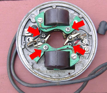
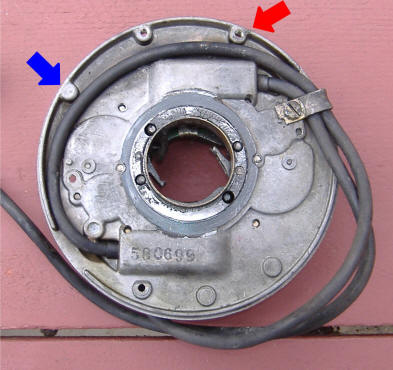
Timing Plate : If you have to remove this timing plate, there are 4 screws that need to be removed from the top that attach the timing plate to the timing plate base. These screws are Philips head and are marked by the red arrows as shown below. Note that 2 of them also hold the coils in place. If you take it apart enough that the coils are loose, be sure that they settle down inside the small protrusions of the plate when you reassemble them.
There is no replaceable friction ring on the 6 / 8hp, as on some later motors. On these there is a non replaceable bronze bushing and it is normal to have a slight amount of slop here. About the only way to tighten is to use a center punch then randomly center punching into the bronze, upsetting it enough to tighten things. Or if you have the time and energy, you could make a THIN steel or brass shim, place it either around the base boss or inside the timing plate, lubricated with grease. If you venture into this, fit it first, maybe even epoxy it in one or the other.
| Timing plate attachment screws & good (replacement) coils |
 |
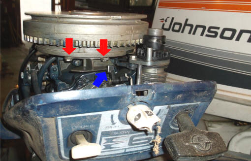
The timing plate throttle cam is screwed onto the underside of the timing plate by 2 hex head machine screws. By loosening these, you can adjust the cam to the carburetor throttle arm. In the photo below these screws are shown by the red arrows. The blue arrow shows the throttle arm to where it is just touching the cam for this particular motor. If your motor is hard to start with the twist grip throttle positioned at START, advance it a bit faster, which may help. Or readjust the cam so it positions the throttle arm a bit faster.
Instructions from a OMC factory service manual on how to adjust the carburetor arm to the timing plate throttle cam are as follows.
(a) If the throttle does not close, either the throttle return spring is too weak and should be replaced or the throttle linkage is binding.
(b) To adjust the throttle cam, advance the throttle control to a position where the cam follower leading (starboard) edge is opposite the mark on the throttle cam. See Figure 3-19 (which is basically the photo below). At this point the throttle valve should be closed. If it does not, adjust as follows;
(c) Advance throttle control. The mark on throttle cam must be directly behind rounded starboard edge of cam follower just as throttle begins to open. See Figure 3-19.
(d) Loosen the hex head screws holding the cam to the armature plate base. Push cam back towards rear of motor, then pull cam forward until it contacts the cam follower. (Choke knob must be all the way in).
(e) Tighten screws and recheck position of throttle valve. Throttle valve should just begin to open when the flat port side of the cam follower passes the mark on the cam."
| Timing plate throttle cam |
 |
Ignition/Electronic Ignition - Post 1977 : These motors changed over to electronic ignition in 1976
Recommended Spark Plugs : The recommended spark plug is a Champion J6C set at .030", however with a well used motor where the rings may be worn and may oil foul the spark plugs, some mechanics may recommend a move to a hotter plug, like the J4C. Or even open the plug gap up from the normal to .035" or even .045" which seems to allow the plug to run hotter and cleaner, especially when doing a lot of trolling.
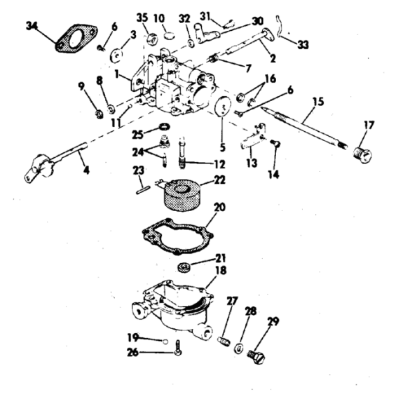
Carburetor : To remove the carburetor, you will need to disconnect the fuel line, the choke lever and low speed knob (sometimes called the idle jet). This Rich-Lean knob just pulls off the finely splined shaft straight forward. After that, you will have to then remove the two top bolts (using a 5/16" box wrench) from the recoil starter spool mounting plate. Very carefully pull the complete starter to one side, BUT just so far that you DO NOT pull the recoil spring out of the base. You have to remove the starter to access the LH carburetor mounting nut and remove that nut. Tip it forward to give clearance for the 7/16" open end wrench to access the LH carburetor retainer nut. Remove the carb cam roller pivot screw and rotate the roller unit off the linkage rod. Remove the RH carburetor nut, slide the carburetor forward off the mounting studs. Replace the starter unit then bolt it back in to keep the spool and the spring from coming a nightmare. However I have had one reader relay to me that he removed the carb without removing the starter, not an easy chore but doable.
The carburetor
shown below is the basic simple standard unit but from about 1971 on using the fixed main-jet
style. Earlier motors prior to about 1970 had an adjustable
main-jet in place of the #29 plug screw shown in the illustration below. You will have to loosen and remove the rewind
starter spool so you can get to the throttle lever pivot nut so you can
then get a wrench on the port side carburetor nut.
| Exploded view of carburetor | Here is a close-up top view of the carburetor, note the pea sized welch plug on top & the 2 lead shot plugs driven in to seal holes on the side |
 |
|
You can usually tear the carburetor apart, soak it in a carburetor cleaner overnight, blow it out with compressed air and reassemble without purchasing a repair kit. Just spraying carburetor cleaner in it does not constitute cleaning even if stripped down. You may luck out and not have to remove the pea sized aluminum welch plug on to rear center or the 2 lead shot sealed passageway covers. If not, then plan B is do it over but remove these plugs and clean everything including the passageways under the se plugs.
The float is varnished and may look cruddy, but if it is still intact and seems to float in gasoline it should function. All that is usually needed is to check to see that the float level is with the bowel flange when assembled without the bottom bowl on and turned upside down. If not parallel, then bend the metal stop tab on the float needle valve area to adjust the float level. If the float is not set at the correct level for the shut off point under pressure from the fuel pump in the carburetor, this could cause motor to run lean or rich.
Some carburetor repair kits cover a wide range of HP ranging from 5hp even up to 20 hp, however do not think just because the kit is the same for a 20hp as it is for the 6hp that they use the same carburetor. The kits may have numerous extra parts, as main jets where you just use the one required for your motor. The breather throat of the carburetor may also be a larger diameter for different hp of motors.
The main jet orifice in the bottom of the bowl has a recess on these models and be full of crud, even though they look clear. On the earlier models (pre-70) there is a adjustable main (high speed) needle jet on the front lower bottom, this needs to be removed for cleaning. On the later carburetors there is a clean out plug in front that you can access this orifice. Use a proper fitting screwdriver to remove the orifice, but be sure there is no debris in or behind it. Be sure the plug screw has a good sealing gasket. This plug is in the same location that the early carburetors had a adjustable main needle jet.
Inspect the idle needle jet to see if it is bent or has the tip broken off, (on these the tip does not come to a sharp point) straighten if need be or purchase a new one. Reinstall this jet needle / rich-lean screw, check the packing nut for tightness to insure there is no air leak around the shaft. The correct way to adjust this low speed needle, is to turn it all the way in until it is lightly seated. You then turn it back out 1 1/2 turns. That becomes a reference point for further adjustment. I like to be able to get a equal rotation each way so set the knob at about what would be 4 on the top. This should give you a basic setting. Once you get it where you want, you can pull it off , then reposition the knob where you want it.
With the motor warmed up and the twist throttle in a SLOW position approximating your intended slow/trolling speed, turn this low speed needle jet in about 1/8 of a turn, let the engine run for about 15 seconds to respond to your new setting. Do it again then wait for the results. A cough is indicative of a rich mixture. Too lean it will just die. When you make this change and the engines either sputters or wants to die, back it off to the the last position then this should be close to the ideal setting. If you go to rich it will cough AND then die. You can now pull the idle knob forward and off the splined shaft, reposition it so that the knob pointer is down so you will have movement either way from this position for fine tuning if needed. This low speed setting does not effect the high speed running of the motor. However it you set it too lean, you may later have a issue with it not wanting to start when it is warm.
One thing if you look at the top of this carburetor, the 1/8" hole at mid-section topish is not plugged with a lead shot like all the rest. My thinking was did I loosen it and loose the plug? Well, after I got it running I covered that hole with my finger and the motor wanted to die. After numerous tries, I decided it was not supposed to be plugged anyway and probably there as a vent to alleviate any vacuum inside the float bowl.
In reinstalling the carburetor to the intake manifold, you may have to position it so that it just starts onto the studs, then start threading the nuts on equally before finally tightening them. What I am saying that there may no be enough room to start the LH nut if you have the RH nut tight.
There is no breather box on this motor as the mouth of the carburetor is open behind the front of the cowling.
| Starboard side view of carburetor showing the idle jet shaft & choke rod. | In the center of the cowling is the Slow-Speed (idle) knob & choke on left |
|
|
|
If when you get it all back
together and can not get it to idle no matter how you adjust the
High/Low speed knob and the idle needle is not worn or bent, you might
be sucking air around the shaft behind the shaft packing nut.
Tighten the nut down to where you still can rotate the shaft. If
that does not do it, smear some chassis grease around the nut threads
and the shaft where it enters the nut. If that helps, then you
need to repack the packing gland area behind the nut. I have some
OLD graphite impregnated water pump packing cord (probably can not buy
it anymore) that I unwind a strand of cord and use it for packing under
the nut. Or you now may be only able to get a Teflon string
packing. You could possibly also use some sting type cord that you
impregnate with grease.
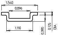
Commonly Lost Part : There is also a Z link rod (shown below) This ties the roller bar unit to the throttle valve of the carburetor. Do not loose it either, or a makeshift one will need to be fashioned from a piece of welding rod. The important thing here is to get the bends just right so that the timing is consistent when the timing plate moves this roller forward to give movement in the throttle valve increasing fuel flow.
In the illustration below is the dimensions for it if you need to fashion one. These appear to all be the same for these 6 and 8 hp motors from 1965 to 1979, AND the 9.9/ 15 hp from 1974 up until about 1986. (And maybe more) after that, there is a different number that has a slight "V" bend front to back.
| OMC # 312830 Link, cam follower |
 |
Fuel Pump : The first 2 years of production of this model (1965/1966), used a different (old style) fuel pump #0380016. This fuel pump was used on other motors as well, like at least the 9.5hp up until 1967, which is shown by clicking HERE. Repair kits seem to be non-existent for these older versions, however gaskets and screens still are. However it is possible to convert over to the later small square style fuel pumps rather easily as the mounting gasket #0388685 is used on both styles of fuel pumps, this part number includes the 2 mounting screws, while just the pump assembly fuel pump, #0397839 is just the same pump. Even this pump has undergone numerous unidentifiable small changes over time. In adapting the newer style regular pump, you will have to replace the two 10-24 X 1 1/2" mounting bolts with 2" bolts. They used the same lower mounting holes as shown on the same LH photo below for the later pumps. You may also have to replace at least one of the fuel lines.
These later small square fuel pumps are pretty universal, the same one fitting most all these small motors up to 40 hp until about 1987. For a link to the rebuild procedure CLICK HERE.
Fuel Filter : This series of motor utilized 2 different fuel pumps, depending on the year of production. Both utilized a filter screen on the intake of the fuel pump. The early model fuel pump, under the center screw surrounded by a rubber ring, which secured the screen cover allowed the owner to access this screen as seen in the LH photo below. When the factory went to the new style fuel pump on this model in 1967, this pump also included a fuel filter screen, as seen in the RH photo below the black plastic inlet is secured by a single center screw. By removing this screw, this fuel inlet cover can be removed, UNDER and pressed into the underside is a fine stainless steel filter screen. Also is a Neoprene gasket just the shape of this cover. The cover and gasket have 4 scallops corresponding to the 4 fuel pump bolts. If this fuel inlet needs to be rotated for better fuel line alignment, it can be rotated 4 different 90 degree locations.
| Here you see the early style fuel pump | Here is the later style fuel pump |
|
|
|
Fuel Tank & Lines : These motors are all new enough (made after 1959/1960), which use the new style vacuum tank and the single fuel line and fuel pump commonly found nowadays.
Recommended Fuel / Oil Mix : On these 2 cycle motors you have to mix the oil with the gasoline to lubricate the internal parts of the motor, so you need to know how much gas you will be needing, add the oil before you fill the fuel tank so that the oil mixes better than just dumping it in after you fuel up. However if that is not possible, then guess, add a majority of what you think it will take, top off the tank and then add the rest matching the amount of gasoline it took to fill the tank. If you are using portable fuel thanks, before hand, when you fill it, make you a stick gauge, by adding 1 gallon at a time, use a clean 3/8" or 1/2" dowel start filling the tank, mark the dowel at each gallon you add, then you can use it as a measuring stick. This way you can refill a partly full tank with the known amount of oil.
Fuel/oil mix on all the OMC motors that have needle roller bearings (this motor included) is 50-1 of TCW-3 standard outboard oil. However I have found that since I troll much of the time, other than getting there and back, I like to use a mix of 75-1 but of a FULL SYNTHETIC blend oil instead of the standard oil. This gives me at least the same or better motor lubrication, plus it gives me less smoke at a troll and the spark plugs last longer before fouling.
A quart has 32 ounces of oil in it. So for a portable 6 gallon tank to fill it using the 50:1 ratio would take 16 ounces, (1 pint) or 1/2 of the quart.
The formula shown below will be on all modern 2 cycle oil sold in the last 30 years or so. On most all of the pints and quart plastic bottles of TWC-3 oils there will be a narrow clear vertical window on the edge of the bottles. On the sides of this window will have numbers representing ounces and Milliliters for other parts of the world. Or you can purchase special measuring containers showing different ratios and the amount of ounces needed.
|
FUEL MIXING TABLE |
|||||
| Gallons of Gasoline |
Gasoline to Oil Ratio |
||||
|
Ounces of Oil to be Added |
|||||
| 16:1 | 24:1 | 32:1 | 50:1 | 100:1 | |
| 1 | 8 | 5 | 4 | 3 | 2 |
| 2 | 16 | 11 | 8 | 5 | 3 |
| 3 | 24 | 16 | 12 | 8 | 4 |
| 4 | 32 | 21 | 16 | 11 | 6 |
| 5 | 40 | 27 | 20 | 13 | 7 |
| 6 | 48 | 32 | 24 | 16 | 8 |
The official OMC fuel/oil mix for most outboard motors in this year ranges has for years been 50:1. This means 50 parts of regular gasoline to 1 part of outboard motor oil. Remember that this was before unleaded gasoline or even possibly an octane rating that was listed at the pumps. Now the recommended fuel is 87 octane gasoline. Early on for the 2 cycle motors the recommended oil was regular automotive 30 weight motor oil, then the outboard industry came up with any TWC oil, which finally evolved into the latest which is TWC-3 outboard motor oil. You probably will not see much of the older TWC-2 oil out there anymore. You can spend your money and purchase OMC oil for about $6.50 a quart, or buy a name brand quart for $3.59. Sure the manufacturers want you to buy their oil, and for a new motor under warranty, it may be advisable to do so. But the consensus from many experienced boaters is to use any good brand of oil, as long as it has the TWC-3 rating, it meets or exceeds the manufacturers specifications. The TWC-3 represents, Two cycle, Water Cooled, type 3 formula. The formula 3 has decarbonizing additives designed to be more compatible with the newer non-leaded fuel.
So from the above information, you can see that fuel and oils have changed dramatically since these motors were first brought out in 1966. In this instance, times have changed for the good, as we now have a better gasoline along with way better outboard oils.
DO NOT use oil designed for your weed whacker or chain saws as these air cooled motors run a lot hotter than the water cooled outboards. The water cooled outboards require the specially designed TWC-3 oils.
Oil Tube for Top Main Bearing : All of the fuel 2 cycle motors the fuel/oil mix passes through the crankcase on it's way to the cylinders. This oily fuel is what lubricates the internal parts. Most of it goes right through the crankcase, carried along with the airflow to the cylinders and burned upon firing by the spark plugs. But a bit of it "rains" out or splatters up against the inner crankcase and piston walls, then drains down settling at the lower main bearing. For some vertical shaft 2 cycle motors, this being one, there is collection pocket around this lower bearing housing. This oil collected in the bottom pocket is pumped to the top main bearing by the alternating suction/pressure of the action of the 2 cycle operation.
It is all accomplished by taking advantage of the different pressures in the crankcase. There is no mechanical pump like what you would find in a four-stroke motor. This oil is routed thru a small oil line to the upper crank shaft main bearing to provide better lubrication to that bearing. This tube is made of brass tubing or rubber (depending on year and model) and is located on the RH side of the block just in front of the fuel pump. Also it is usually painted the same as the power head, which makes it even a bit harder to identify unless you know what you are looking for. This tube needs to be free and clear for the oil to be moved upward. And if there is a leak in the line, especially at the top, you may be sucking enough air to disrupt the idle air setting.
The black rubber vertical tube in the photo below is the overboard water conversion mentioned later in this article.
| The oil transfer tube is shown here by the red arrow on the starboard side of this motor |
|
|
To Start It : These points and condenser motors when cold usually won't start in the minimum throttle position until you advance the throttle twist grip to line up with the "start" on the sticker at the base of the throttle grip. If you are in doubt and/or if the markings have disappeared, then advance it to about a medium/fast setting as it will start if set faster, but it WILL NOT start if set lower. The reason here is that with any old motor that uses the throttle gear cog linkage system to the timing plate, once things get worn, this will throw the motor's timing off (retard it).
Pump up the fuel line primer bulb until it becomes hard. Pull the
choke knob out and with a quick effort pull the starter rope. If
everything is functioning, it should start, possibly on the first pull,
but usually within the first 3 pulls.
Low Speed Stop
Screw :
The later CDI electronics motors have an adjustable stop screw on the bottom gear at
the end of the rod that moves the advance mechanism (base of the
handle).
To Stop It : There is no kill button on these motors up to 1979, you just retard the throttle twist grip as far clockwise as it will go and the motor should die, it not, then choke it to kill it. At 1979 there was a kill button located below the idle adjustment knob on the front cowling.
Remote Controls : According to this parts website, http://www.marineengine.com/parts/johnson-evinrude-accessories/index.php?year=1978 apparently remote controls were made, but it would seem that the twist hand throttle would need to be disconnected, so you would have just the remote. Because trying to operate the throttle cable where you are type trying to move the twist handle gears from the back side would not have enough leverage/pressure using a remote cable system.
However a
Problems : On the motor I was working on, after trying to start it, then checking spark (or non spark for one cylinder), then when I got this motor together enough to run, it had more problems, which appeared to be timing and carburetion issues. The timing plate was so loose on the pivot post of the block that it wobbled every time the flywheel rotated and the flywheel magnet came close to a coil. This bronze bushing is cast into the timing plate which is not replaceable. The only other thing to do would be was to use a center punch and make many punch marks internally around on the inside of this bronze bushing trying to tighten it to the power-head boss.
In my junk box (before I cleaned the shop and sold the aluminum scrap) I found a timing plate assembly off a older QD 10hp with the coils, points with condensers still attached. They looked very similar, WHAT THE HECK, presto the plate measured the same and even fit the pivot post a lot tighter than the one I took off. There were items like the timing cam plate and throttle linkage pivot that were different, but once these were removed the others off the 6hp bolted on with one difference. The only real difference was the mounting holes for the timing cam plate. The 10hp was rotated to the right one bolt hole. However there was no hole or threads there for one end of the 6hp timing cam. The casting boss was there, being cast into the base. I drilled and tapped a #10-24 hole centered in the blank boss, bolted the 6hp parts on, presto, it was good to go.
The only other thing to do to tighten this.
Modifications to Timing Plate : In the LH photo below shows the original 6 hp timing plate. The 2 threaded screw holes are as needed. The 10hp plate needed a new hole & threads at the BLUE arrow. Then the timing cam was simply shifted to those 2 holes & the RED arrow hole was abandoned. So my guess is that this timing plate was pretty universal for many motors in this size range and vintage.
I used the 10hp points, (they were better than mine), the same condensers and coils off the 10hp also.
| Bottom side of timing plate | Top of timing plate showing ignition system |
 |
|
The throttle cam, at least on this 1972 version was just a plain plastic post. The newer ones (at least in the 1978 parts catalog) show a roller on top. I understand why, as this solid plastic cam had 1/16" wear at the timing cam mating surface, (possibly because of the loose timing plate) creating a initial timing problem. I did a patch repair using 4 minute J_B Weld epoxy, filling the worn hole. In looking at the factory service manual for this model they recommend lubricating this mating surface between this lever and cam.
Recoil Starter : The recoil starter uses a rope type spool system that works very much like an automotive type starter unit only manually.
Here is one instance where you may have problems achieving a compression test high enough to indicate a good reading. This spool rope type starter seems to not provide a lot of speed in comparison to other types, and you may need to pull the rope with the idea that you are mad at it, no love pulls here if you want it to start with any reasonable regularity. If the compression is low for any of a multitude of reasons the motor may be harder to start, so all your adjustments need to be right.
Occasionally you will find the starter rope frayed. If so, replace it before it becomes broken as your headaches will be a lot less. If you are not near a marine dealer/repair shop, you might take some of the broken rope and try a lawnmower repair shop to see if they have anything in a size near the broken one, and 5' will do it.
While you have it out of the pull handle hole in the lower front cowling, take a look for any wear. If so it will usually be on the top of the hole and will be pear shaped with the narrower part where the rope has worn. This motor does not have a brass sleeve like the later models do, so it may be best to ream that out a bit to keep the sides from wearing (creating more drag and chafing of the new rope). You can ream it by drilling, or just using a round powersaw file to clean it up. If you do, be sure you do not leave any sharp or even rough burrs which will damage the new rope. I see no real need to now try and install a brass rope sleeve through this cowling as what wear you see only took 40 years to accomplish.
| Port side view of the spool type starter |
|
|
To replace the rope (if it has not become totally broken), you should first remove the spark plug wires for safety. The following was taken from a 1971 service manual.
"(1) Pull the rope out as far as you can, then allow it to retract less than one revolution until the rope end of the spool faces the port side of the motor. Lock the starter in this position by lifting the starter pinion gear upward to engage the flywheel ring gear, and slide the slightly spread handles of a pair of pliers under the gear, holding the gear upwards and into the flywheel gears. (2) remove the starter rope handle. (3) remove the rope from the spool. (4) Replace with a new rope, which needs to be 56 1/4" long, then burn the ends with match for about 1/2" to keep them from unraveling plus to be stiff so they will hold in the spool or anchor. Thread the rope thru the slot in the spool AS IT CAME OUT OF. (5) Thread the rope thru the motor cover and install the handle. (6) Hold the starter rope handle to keep it from rewinding too rapidly, remove the pliers allowing the rope to rewind normally.
To remove the starter unit from the power head, (1) pull the starter handle and form a knot in the rope to prevent the rope to recoil while removing the handle. Remove the handle. (2) remove the rope. Hold the starter spool then slowly allow the starter main spring to unwind completely. Remove both the bearing head screws and front spring retainer plate screw, allowing the plate to drop enough to release the starter spring. Lift the starter unit up and away from the powerhead. (3) remove everything, clean and inspect for wear.
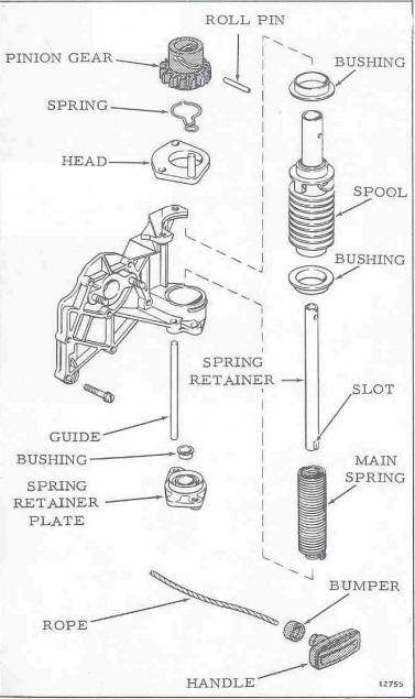
To reassemble the cleaned starter unit, (1) place the upper bushing and starter head with the pinion gear spring onto the spool. (2) Insert the spring retainer in the spool. Align the slot in the gear with holes in the spool and spring retainer. Insert the roll pin with its split seam in a horizontal position to avoid dragging against the slot in the pinion gear. (3) DO NOT oil the gear or spool, this will attract dirt, causing pinion to bind on spool. (4) Insert the spring into the bottom of the spool, turn to engage with the slot of the spring retainer.
To replace the starter unit to the powerhead, (1) Place the bushing in the spring retainer plate. (2) Twist the spring to lock the inner spring onto the spring carrier. Pull the end of the outer spring out of the spool and hook it onto the retainer. (3) Place the guide in the starter plate. Insert the spring hook into the retainer plate slot. (NOTE if the spring hook has broken off, you can re-bend the end). Raise the retainer plate to hold the spring. Install the front retainer plate screw and tighten the rear screw. remove the spring from the spring retainer. Install the starter assembly to the intake manifold. (4) Place a heavy duty screwdriver or a brace with a screwdriver bit in the slot in the top of the starter spool shaft. Wind the main spring 16 1/2 turns COUNTERCLOCKWISE. The rope anchor hole in the spool should face to the port side of the powerhead. Raise the pinion gear to engage the flywheel and lock it in position with pliers. (5) Install the rope as described in the rope replacement paragraph."
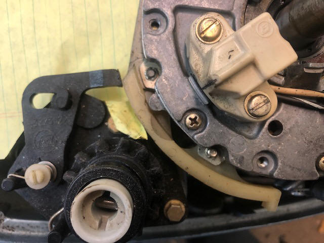
No Starter Interlock on Early Motors - Pre 1976 : On these early motors they DID NOT have a starter interlock built in so that you could start the motor in any gear but neutral. The later starters did incorporate this devise (just a modification on the upper starter bracket and a cam on the timing plate). This is a black plastic arm that pivots onto a cam on the timing plate, when rotating the twist grip. This arm pivots (from it's visible screw-head anchor) forward engaging the interlock preventing the starter rope to be pulled if in a fast position. In the RH photo below you can see the pivot arm just starting to engage on the timing plate grayish Nylon cam. Here yellow tablet paper has been inserted below to allow for better viewability. This change came about at the same time as they went to electronic ignition and top cowling change.
| Early starter | !977 & later starter interlock |
 |
Personal Observations on Replacing The Starter Unit : If just the rope broke, DO NOT remove any of the starter parts. It is not as easy as described above to get the spring back in it's proper location, especially if someone previously had tried to repair it AND wound the spool clockwise, distorting the spring. If just the rope is broke, rewind the spring as mentioned above (however it is hard to determine in what position the spool should be in before you start winding it the 16 1/2 turns). Once you have it wound under tension, replace the rope and go from there. Lets explain winding the spring wrong, damaging it. This spring is ONE spring, with an inner wound coil AND a outer wound coil. If you try to wind the spring as it appears it should be to retract the rope on the spool (just looking at the outer part of the spring) --- WRONG --- because of it having the inner and outer windings as a continus wire, the inner winds one way, and the outer (which attached to the spool, the other way. Any unwinding a coil spring (especially this one) damages it.
If for some reason you removed the starter unit and found some of the bottom outer coils were considerably larger that the uppers, someone has tried before to replace it, but wound the spool CLOCKWISE. This will make it hard to reassemble where you need to get the outer lower hook in the proper slot of the retainer plate AND at the same time this hook into the underside front recess of the lower main housing. You may have to try to reshape some of these coils using pliers. Then to assemble, (with the aid of a helper) the spring needs to go into the lower hole in the main housing, and the retainer plate brought up from the bottom so it allows the spring's hook to rest in the groove in the main housing, all the while you need to slide the retainer plate up AND the spring down so the spring's tail is secured out through the retainer's slot AND the housing. Insert and tighten the two lower bolts.
Now you can slide the spool assembly down being sure that the slot in the shaft's lower end straddles the inner spring's bent lower tail. You will have to tip the head up slightly so it will accommodate the upper end of the guide rod. Now you can insert and tighten the upper two bolts.
You can replace the rope as describe above. Do not be surprised if you will have NUMEROUS tries before getting the spring in properly and of inserting the rope.
By the way, this spring is not cheap, and from what I can find, if you do order one, be sure that you have ordered the right spring for the proper year of motor, as it appears the first two and 1/2 years used #311265 at a price of $107.99. In 1968 there was a change during the year and series numbers can mean part changes. Mid 1968 on to 1977 used #314500, while 1978 and 79 used #323571 is obsolete, being replaced by the complete spool assembly, including the spring #390187 at a price of $189.99, as of 03/2022.
I have heard from one person who had
problems with the plastic pinion gear not wanting to engage the
flywheel gear teeth. Possibly someone greased the
plastic pinion gear shaft, (which is a NO NO as the pinion needs to
be free on the spool shaft). What raises the pinion is the
roll pin (seen in the exploded view below) that goes thru the
hub/shaft and into the helical slots (both sides) in the plastic
gear. As you initially pull the rope the gear raises (being
camed up by the roll pin). Be sure it is free of gunk.
Maybe someone has broke or used a shorter roll pin that does not
engage the pinion slots properly ??
| Exploded view of the 6 hp starter unit. | |
 |
Water Cooling System
: These outboard motors are water cooled, requiring a water
pump system. They utilized a
screened water intake BEHIND the prop, using it's motion to force water up
into the water pump (as shown in a photo below). This was well known in those days and the
mechanics put the motor in a tank (WITH THE PROP ON) to do a test. Now
after 50 years, there seems to be many Do It Yourselfers who are new to
outboards and do not understand this system, who put the motor in a small
garbage can, but take the prop off so it will not cut the can. This
may allow your motor to run, but not for an extensive amount of time because
of the now underwater exhaust bubbling in the can, which disrupts any water
flow (because of a lot of air bubbles) up into the pump.
There was an aftermarket water intake attachment, they are now long extinct, but a do it yourself unit is shown below.
Also the cooling system has to have water flowing through it.
This could be restricted at the intake, as mentioned above, or in side the
motor, especially if it has been used extensively in saltwater. Or used
occasionally in salt water and not flushed, then sat for some time, allowing
salt crystals to build up and block passages. So first off if the motor
is getting warm or not exiting exhaust water, it may be beneficial to
check/replace the water pump impeller. If you still get the suspicion
that there is still no/or minimal water flow, look deeper. First would
be check the thermostat, these are simple to get to in
relationship to other repairs as the thermostats are a thing that needs
attention quite often. They are in a cavity in the top of the head and covered by a bolt on plate. Pull them out and carefully
clean if there is any debris covering/in them. If they are coated with
salt crustation, sometimes a soaking in ordinary Vinegar will loosen that.
Once clean to check if it is functioning properly, place it in a pan of water
and bring it up to a boil. Most of these are designed to open at from
145 to 165 degrees. I fit is stuck, then time to install a new one.
If all that does not help, then pull the head off and check/clean any
debris out of the water jacket cavities around the cylinders and inside the
head. Most all of these smaller motors
have a water jacket cover on one side of the motor, if so pull it off and
again clean any passages.
If your motor is old enough and does not have a tell tale pee tube
(overboard water indicator), I suggest that you install one (again as shown
below) so you can see the
actual stream of water. This is not all of the water, but only a portion
of it.
Water Intake :
These motors main
water supply to the water pump comes from a screened tube right behind
the prop in the exhaust outlet. Water is forced into the
screened intake to the water pump by the prop thrust. Some users
report that when running these motors in a barrel, (usually a small
one) that the prop has to be installed and usually in gear as apparently
they need to get more water pushed to the water pump by the prop to
get enough to cool when running at over an idle.
If you
have water starvation at higher RPMs, is the inlet screen in place in
the leading edge of the exhaust snout? Is the plug in place at
the bottom where they inserted it? If this plug is missing, it
will starve for water at speed.
There is a also a stainless steel reverse water intake plate with a few holes near the water pump area on the left side above the cavitation plate shown in the photos below. Flush kits for this motor are rather scarce. There is really no provision currently available for a easy muff system to run this motor out of a tank. But there is hope.
Thermostats : These are the same on most motors from 5hp to 55hp for years 1959 to 1994. Since these motors are usually used in fresh water only, they can usually be removed, cleaned up with no problems. Do not run a motor without the thermostat as the motor will not run in a high enough temperature range to allow the motor operate at it's efficiency level, plus if you troll it, a lot the spark plugs will foul a lot because they are not up to a proper operating temperature. And you will have a lot of black oily residue dripping off the lower unit/exhaust.
Possible Overheat Problems at Troll or in Tank : Do not remove the prop if you decide to run this in a plastic garbage can. If you do take the prop of so you won't damage the plastic can, you will have such a confined area and when running, the exhaust fumes/bubbling will create enough air bubbles that the water to the water pump will have more air than water and starve the pump. You need the prop's thrust to push water up into the water pump.
If you happen to have the motor overheating at slow speeds, you might consider looking at the water intake screen tube which is situated in the lower unit directly behind the prop. This is placed here so that the prop thrust pushes fresh water into this screen tube. If the factory, or more likely a subsequent owner may have repainted this area which inadvertently blocked enough of these screen holes to partially block water intake at a slow speed.
This screen would be hard to remove AND save after many years, so using a SMALL nail, icepick, or similar tool, you should be able to poke enough of the plugged screen holes without breaking the screen enough to clear it to make a difference on the water intake. Ideally would be to remove the gearbox from the motor and sandblast the crud out of the screen, then be sure to wash it out before reassembly of the water pump.
| Pretty well plugged water intake screen with paint & debris |
|
|
No Overboard Water Indicator on Early Motors : The 1972 motor I was working on did not have a overboard water indicator (pee hole) which did not came into being on these motors until 1977. They do have a "water outlet" as seen in the illustration below. This outlet allows for some outlet water to mix with the exhaust gasses to cool the housing and at the same time allows only a small amount of exhaust with some spitting water, as an indicator of sorts, some may call it second exhaust port, however in actuality, in these smaller engines you could say it is an idle bypass, because at idle speeds there is not enough exhaust pressure to overcome the under-water pressure out the larger hole near the prop.
I have looked at other newer motors and their indicator line comes off the side plate cover. However 3 of my side plate bolts were seized, with the chance of twisting them off being very likely and 2 of those were in a hard place to get to at the bottom. Plus I did not really want to tear the powerhead off the midsection to get to the possible twisted off bolts for repair.
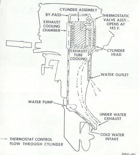
Time now for Plan B, I have traced the water flow in the service manual and found that a simple modification to the thermostat cover can be made to create a water indicator hole line. The thermostat cover is at the top rear of the head. It uses 3 bolts for attachment. There is a bypass flow from the motor's intake to behind the thermostat. I reasoned that if this bypass was there to relieve pressure buildup before the thermostat opens, that I could tap into it and not make any change in the thermostated cooling of the motor itself.
| Water passage thru this motor |
 |
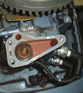
If you take this thermostat cover off then Heliarc weld a slight amount of weld (even using JB Weld epoxy would work) on the top side at the same location that the bypass enters from underneath, you can then drill and tap for a 1/8" pipe tap, USING THE BYPASS HOLE ON THE UNDERSIDE AS AN ALIGNMENT GUIDE. DRILL FROM THE UNDERSIDE, CENTERED IN THE EXISTING ROUND RECESS. You need to add this material because the cover is so thin at that location that you possibly can not get enough material to give more than a couple threads for the new outlet Ell. Now you can screw a 90 degree pipe elbow (it is best to purchase an OMC Ell #321886) which are made of nylon, which are recommended as they are more forgiving if you need to tighten more into this hole and add rubber tubing to the starboard side then drill a hole in the lower rear cowling for it to exit.
For the hose, I have found that automotive windshield wiper hose works great.
| Shown here is the thermostat with the cover removed & you can see the bypass water inlet hole just forward of the stat | Location of the new fitting showing the threaded Ell on the bottom inside of the thermostat housing cover using the existing water channel entrance as a drill location |
 |
|
Unforeseen Problem After Overboard Water Conversion : One thing I found after this project was done was that now the upper cowling would not seat far enough down for the to latch to function. It appears that this Ell now just happens to sit exactly under one of the 1/4" bolts that attach the lifting lip to the motor cover cowling. You may have to shorten the threads a bit, allowing the Ell to be screwed in deeper. However if you purchase a 1/4"X 20TPI X 3/4" FLATHEAD stainless steel bolt, then countersink the fiberglass at the hole to accept the taper under the flat head, you will just have enough room for clearance.
| Rear view of the placement of new pee hole elbow & line on the top of the thermostat housing | Note the new countersunk flathead screw on the left needed for clearance of the new Ell fitting. |
|
|
|
Another Method of Installing a Water Indicator : The reason I did not do the factory method on the above conversion was that 3 of the lower water jacket screws were seized. I did not want to have to pull the powerhead to be able to get at these broken screws if it came to that.
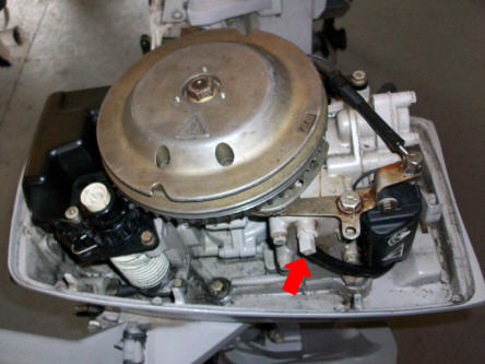
Now, I have discovered that IF you are careful and drill the initial hole with a smaller drill AND smear some chassis grease on the front of the drill bit, you can recover most of the aluminum chips. Move up to the the proper hole ("R" drill .339" or a 11/32 .344") for the 1/8" pipe size Ell and again smear the grease on the drill bit. Then again smear grease on the 1/8" pipe tap when tapping, but don't tap really deep as pipe taps are tapered allowing the pipe to be screwed in deeper, tightening it, creating less leakage the deeper it goes. Since this material is possibly rather thin, only go part way in with the tap, try your Ell and adjust the tap depth if needed.
Locate the hole near the top of the water jacket as seen in the photo of a newer motor shown below. As a note, the pre 1993 9.9/15hp motors have the Ell low on their water jackets and are susceptible to minute debris plugging the Ell. If this Ell is located higher then it appears to be less susceptible to debris plugging.
| 1984 6hp water indicator tube off the water jacket cover |
 |
Shift Lever Breakage : A common problem is a broken aluminum metal gearshift lever. The motor falls on it's side and this breaks where the steel shaft is molded to the alloy shift handle. OR if the operator is not aware of the construction of the gearbox/shifter slider cutch dog system and FORCES the handle, it could break off. A pain to fix usually unless you know a good aluminum alloy welder. The shifting lever rod runs through the exhaust so the little cam that transfers motion from the lever to the rod corrodes and it is just about impossible to remove the screw without damage. A new shift lever is expensive, if available, and of course you have to remove the powerhead to access it.
Twist Grip
Problems
:
The twist grip retainer screw threads can become cross threaded upon
reassembly if you are not careful. About the only way to correct
this is to run a 12 X 28 (this is an uncommon, but standard size)
tap thru to clean up the old threads. Then be very careful when you try to get
this screw started because the handle is under spring tension. I
have found that it is best to get the threads aligned with the hole in
the handle as best you can while holding the handle rearward as tight as
possible AND then using a small Philips screwdriver or similar tool to
reach in thru the handle hole and try to align both while holding tight.
Then get the screw started as straight as possible.
These motors DO NOT share all the same problematic throttle twist grip gearing system as mentioned extensively in the 9.9 articles, in that these series you can raise the handle up while changing speed without jumping the gear teeth. This one used the early gears made of cast bronze, I had to braze new teeth onto the broken ones and hand grind them with a Dermel tool to match the originals.
Tilt Lock : This motor has a small lever lock in front under and behind the clamping screws to hold it in the running position. This is so if you put the motor in reverse and give it some power that the lower unit will not pop up and out of water. Sometimes these are called the reverse lock arm....usually labeled "Lock" and "Release". To tilt the motor up, press down on this lever, putting it in the release position. This will allow you to move the engine up manually. But it does not have a tilt lock to hold it up, only a nut on the end of the pivot shaft that is a tightened so that there is enough friction to hold the motor up while yet being able to be tipped back into the water without a lot of effort.
Move the engine back down and it will click back in place, or it should, if the spring is still functioning. However you may check to see that it does back in the "lock" position before you run the motor.
To change the motor's angle on the transom, tilt the motor up as described above. Then while it is up, inside the mounting brackets you will see a 1/4" rod going horizontally between the two outer brackets. There are 4 notches in these brackets that the rod can be moved to to change the angle the motor is mounted to give better performance.
In the photo below, you will notice a key type slot in the center of the carrying handle. This was for the older method of mechanical steering (drum and cable) where the double eared spring connector of the steering cable could be mounted in a quick disconnect system.
| Here the tilt locking lever is shown, to unlock & lift the motor up, push down on the lever |
|
|
Motor Mounting Clamp-Screw : The 2 clamp screws that hold the motor to the transom WILL need service occasionally. The pivoting handles of these screws should have oil placed on the pivot pins from time to time to keep them from seizing up, then breaking off. To service these screws, it is best to remove them from the bracket. There is a smaller screw that comes in from the rear and is screwed into the rear of the main clampscrew, holding on the large cupped washer in place. Use a 7/16" socket wrench to remove this smaller screw, then you can unscrew the clampscrew and totally remove it from the front of the bracket, clean, grease and replace.
If the screw comes out hard enough to gall the threads in the bracket, you may need to run a 5/8 NC (National Course) tap in to clean up the threads. If at all possible you need to try to save what you have here as to replace these with new parts, you can no buy just a handle or screw, but the hole unit with the washer which costs a mere $75 EACH.
Motor Mounts : These upper rubber motor side mounts are pretty well designed, a rubber block with attachment bolts molded into them last a long time and are externally mounted. They are held onto the base part by two 1/4" bolts (on opposite ends) and by a single 3/8" stud on the center outer side. The starboard upper mount is pretty accessible, but if your LH (port side) needs replacing the front inner bolt is buried behind the throttle linkage bevel gears. To access this mount, you will have to remove the throttle linkage arm to the timing plate (held in by 2 screws of a strap clamp at the upper part of this arm), then remove the bevel gear that it meshes with on the bottom. You might even have to remove the throttle drive gear. Now you can reach in and get to that front mount base screw.
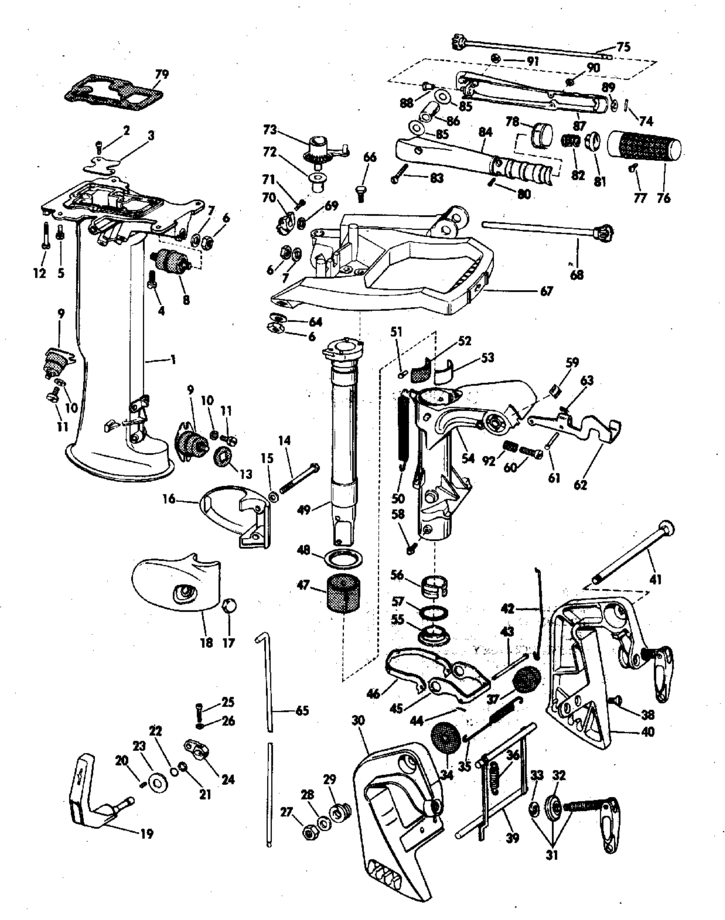
If the upper front mount needs to be replaced, that will entail removing the exhaust housing from the transom clamp assembly, which may not be that easy if you have an old neglected, corroded motor, however the exploded views illustration seen below may be of some help.
Exhaust Housing/Mounting Assembly : The exploded views shown below may help you in the assembly of these parts. However Good luck trying to remove the carrying handle or transom bracket units as you have to remember these motors MAY HAVE BEEN ABUSED FOR OVER 50years and trying to remove some bolts (without breaking them off) may be near impossible.
And to access
most of this, you need to pull the powerhead, even for pulling the
carrying handle, which is bolted onto the pivot post.
| Here is shown the exploded view of the exhaust housing/tiller handle & mounting clamp unit |
 |
Removing the Lower Unit : There are 4 bolts that hold the lower unit to the exhaust housing, remove these. The lower unit should drop down maybe 3/8", but probably not enough to access the shifting rod coupler bolts through the gap created. Shift the motor into reverse, as this allows the lower unit to drop down about 3/4", enough to access one of the (2) 1/4" fine threaded bolts that are threaded into a brass coupler block which connects the upper to the lower shifting rods as shown by the red arrow in the photo below. You do not have to remove the upper coupler bolt, usually just the lower one. Once this lower coupler bolt is removed, if the lower unit will not drop enough to come loose, (these motors are different than most) pull your spark plugs and pull the starter rope or rotate your flywheel, or the prop while pulling down on the lower unit. This will rotate and allow the shaft dowel pin to align with a slot in the upper mid-section seal, (rotating sometimes up to 1/3rd of a rotation) the drive shaft now can come free and the whole lower unit comes off like all the others do.
If the gearbox unit does not want to drop down then the copper water supply tube from the water pump may have become corroded into the two rubber grommets on both ends of it and you may have to use a couple of large screwdrivers to persuade it. With the lower unit down and off you can then start working on removing the water pump.
With the lower unit off the motor, you can now remove the 4 smaller bolts that secure the water pump housing to the lower unit. This water pump housing can now be slid up and off the driveshaft revealing the internal working of the water pump.
With the water pump off, do not try to lift the unit by the driveshaft as it will pull out of the lower unit AND if you allow this unit to tip, gear oil will run out the driveshaft hole. The driveshaft is basically held in place by the impeller drive key when everything is bolted together. And when in the final assembly to the upper part of the motor, the driveshaft is captivated between the bottom splines of the crankshaft and the splines in the gearbox driven gear.
| The lower unit being removed with red arrow showing shift linkage coupler screw that connects the upper & lower shifting rods |
 |
Water Pump Repair : This water pump and gearcase is very similar to the other OMC motors up to and including the 9.5, 10, 15 and 18hp motors made up until about 1973.
Water pumps are basically the same design as still used on all outboard motors. These impellers are a larger diameter than on some of the later unitized lower units, in my book they appear to be able to still function even after many years of usage even after becoming less flexible. The one thing the early units, (as with this one) was the pot-metal cast housing & was in normal deteriorated condition being well worn inside. It is then recommended to replace the pump unit with the newer stainless steel liner version if you have plans on keeping this motor in your stable for some time.
The exploded views in the service manual (shown below) show a gasket, seal, spring and washer at the upper part of the driveshaft. It calls it the driveshaft seal. The upper part has a round gasket, then a metal washer/plate, an O-Ring, then a ceramic seal, then a coil spring that the driveshaft will slide inside of, then on the bottom a cupped washer that holds the spring. When the driveshaft is pushed all the way up into the crankshaft splines, the "seal support pin" (dowel pin) will then put pressure on the spring loaded washer pushing the seal up then pushes these all together creating a lower crankcase seal. Rather odd arrangement, as of yet I have not removed the powerhead to get a up close and personal look.
However if the seal is damaged, the powerhead will need to be removed as all of this seal unit is put into the exhaust housing recess and from the top side before the powerhead is bolted down. This seal unit is #1 thru #6 in the illustration below, with the cross pin being #8.
| Water pump & drive shaft exploded detail taken from 1972 OMC service manual |
|
|
Below is a photo of the older style water pump housing used on this motor that does not have the stainless steel inset. Note that there is wear on both the top and bottom plates. This particular pump did not function very well. Matter of fact it pumped water so sporadically that I modified the motor to a newer pee hole style because I was unsure as to the real condition of the pump. I suspect there was just enough wear on both sides of the impeller that it was bypassing water somewhat. Also inside the impeller housing in one location were 2 small holes about the side of a matchstick. Behind them were indications that they had also worn the impeller.
The newer motors at about 1978 used a nylon water pump housing and stainless steel impeller liner which is far better than the original metal water pump pot metal housing. This new housing can be retrofitted to the older motors. The 1979 water pump used a different water pump with a smaller impeller diameter.
Some might call me frugal and from my scavenging listed above, maybe so, but with the price of a new pump unit at over $75 and this being an old motor of unknown qualities, I did not want to invest a bunch of money before I found out how it eventually may or may not run. Being retired and on a fixed income also could have also been somewhat of a determining factor.
Pawing thru my junk box again, I found water pump parts of a older QD-19 10hp. The stainless base was the same exact size and shape as the 6hp only better condition. The housing was the same only the center hole indicated a larger drive shaft was used, it however was in worse shape than the one I took off.
| Original worn water pump housing & plate |
|
|
I salvaged the 10hp bottom plate and placed the existing 6 hp housing in my metal lathe. Mind you that one of my professions in the journey of life was a machinist. I dial indicated the impeller hole concentric and square with the four jaw chuck, then reached inside with a boring bar removing about .008" off the unworn center (just enough to clean it up) to match the wear of the impeller vanes being careful not to take to much because the impeller hole is now eccentric to the lathe chuck. Then I removed about .015" off the bottom flange to compensate for any possible wear and what I removed. Hopefully the new impeller would be a tight fit like originally designed.
I then mixed up some JB Weld and filled the 2 holes in the aluminum casting. Later I sanded them down matching the rest of the inside housing and cleaned up the non-wear behind the holes.
A new water pump outlet grommet that I had left over from a previous 9.9hp repair (same grommet) was installed before final assembly.
| Water pump being reassembled, note the upward protruding shifting rod | Water pump assembled for photo purposes, showing water outlet tube. In actual reassembly this tube needs to be inserted into the upper grommet first & then aligned into where it is shown here on final assembly. |
|
|
|
Water Pump Re-Assembly : I have found it best to inset the impeller into the housing with the ears rotated as if the motor was being rotated clockwise looking from the top. I usually lubricate the vanes with a slight amount of oil or Vaseline. Slide the housing and the impeller down the driveshaft. Be sure to place the impeller key in the shaft and slide the housing farther down onto the key. Some keys are made in the from of a Tee, while others are simply a short round steel rod. The bottom peg is rounded that goes into a hole in the driveshaft, leaving the top of the tee which is rectangular slide into the square notch in the impeller. It wants to turn sideways slightly enough during assembly that you need to have it very close as the 2 slide together to assure it is right. Bolt the housing down to the lower unit base.
Driveshaft Alignment : This motor uses the same lower crankshaft seal as the 5hp of the same years EXCEPT it has a seal retainer compartment on the underside of the block in the upper exhaust housing area that contains the seal assembly. In the 5hp, the seal can/will fall out when you pull the lower unit/driveshaft down and out.
Upon reassembly, the only thing different than the normal water pump reassemble was that of aligning up the 3/32" dowel pin (part #8 in the illustration below) in the driveshaft upper section with the slot in the midsection containing the seal assembly just below the powerhead. This pin slides up thru a slot on the lower part of the powerhead and puts pressure onto the bottom of the lower crankshaft O-Ring seal forcing it upward to make the seal complete against a stainless steel plate that rests against a gasket on the lower block. You can shine a flashlight up the housing and see what needs to be done to align the dowel. As you align the driveshaft, you also have to align the water pump tube in the mid-section into the water pump outlet grommet.
Number (3) is the actual O-Ring seal, with the pin pushing the (#4) retainer cup and spring forcing the seal up to bear against the #2 plate. The lower spring retainer washer (#6) has "bumps" on the bottom of it. The pin (#8) drives against the bumps, turning the washer. Friction turns the spring and O-Ring seal. The 303355 gasket keeps the plate from turning and seals it to the bottom of the crankshaft.
This same seal assembly is used for the older 5.5hp and 7.5hp motors as well.
| Lower crankshaft seal assembly | Actual View of everything slid on the shaft. However on the assembled motor, when you pull the lower unit, you will never see anything other than the cross-pin, as the seal assembly stays captivated in the upper exhaust housing |
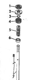 |
|
If someone replaced the driveshaft with a older (pre 1968) shaft, it may not have this dowel pin which you will need to drill and install a pin in order to make the seal function properly. You can tell if you need the pin by using a flashlight then looking up thru the exhaust housing and inside at the driveshaft hole in the bottom of the powerhead. There will be a slot on each side of the shaft hole which you should be able to see the lower brass part of the seal thru these slots. If you do need to drill this pin hole, it is 14.80" from the upper edge of the gearbox or 2.366" down from the top of the shaft, the pin is 3/32" or .0935" dia. This dowel pin is 3/4" long.
Reconnecting the lower unit/driveshaft to the exhaust housing/crankshaft, the pin mentioned above, as long as you don't force it to the point of breaking, just have the lower unit in gear with slight pressure upwards, then turn the prop so that the driveshaft turns, the pin aligns with the slot and it pops in, you're good.
Now shift the lever into reverse, also pull the lower unit shifter shaft UP, so the shift linkage coupler can be aligned and then screwed together using the coupler.
The water supply tube to the motor from the water pump is a short 10" slightly bent shape seen in the photo above. This tube may come out of the upper grommet upon disassembly. If it does, replace it in to that upper grommet in the exhaust housing before you try to slide everything back together. It is about impossible to align this tube to the upper grommet AND get the shift coupler AND the driveshaft rotated right all at the same time unless you install the water tube in the exhaust housing first. Doing it this way using a flashlight if needed, the tube and lower grommet coming out of the water pump housing, the shifting coupler can all be seen at the same time at assembly.
Be sure that you get the removed shifter coupler screw back into the coupler with the shifting rod all the way into the coupler so that the retainer screw goes thru both the coupler and the grove in the shifting rod. It may be prudent to slightly spread the slit in the coupler to allow the coupler to more readily slide over the shifting rod which helps to easily located into proper alignment. Otherwise your neutral will be forward and reverse will be neutral.
One bit of advise, use one of those mechanics flexible shaft fingered pick-up tools to place the coupler screw in the coupler because now you have a narrow space about the size of the head of the screw, between the mid section and lower unit and if you drop it into the lower unit cavity, you have to pull it back apart & shake the screw out to start over. Then a good fitting screwdriver can finish the job.
Aftermarket Water Flushing Adapter Cover : These motors main water supply to the water pump comes from a screened tube right behind the prop in the exhaust outlet which utilizes the thrust from the prop to push water up to the water pump. This method of water intake does not allow the newer type of flushing muffs to be used. At Soon after these motors came out with this type a water intake system, Tempo made Flush Kits #918FAA (as seen in the photos below) for a while for these motors, but now are not currently made and are rather scarce IF THE PERSON EVEN RECOGNIZES WHAT THE ARE. Those of you who frequent garage sales may be on the lookout for these.
| 1984 Johnson 6hp with Tempo Flush Kit in place |
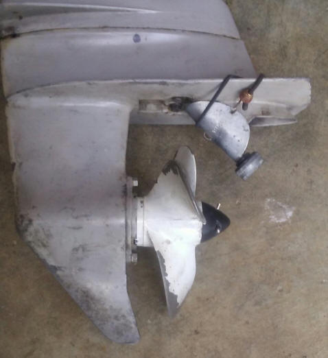 |
This unit is 3" long not counting the hose nut, and lined with what appears to be 1/8" sticky backed foam, which provides some sealing and is held in place on the motor by a mini bungee cord.
| Tempo #918FAA front view | Tempo #918FAA rear view |
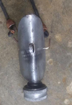 |
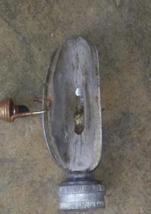 |
But there is hope. On the LH (port side) of the exhaust housing just above the anti-cavitation plate there is a thin stainless steel plate (the factory nomenclature is water bypass cover) which is held in by 2 screws. In this plate are 4 small clamshell type scoops that is designed to put water into the water pump when the motor is in reverse, as shown in the photo on the left below. This is common to many different size of these motors up to 10hp in these years up to about 1974. It was designed to supply water to the water pump when the motor was in reverse, however some motor owners think it is there for added water intake during forward running so you may see them in stalled either way.
The right photo below is from a 10hp is an commercial aftermarket adapter (no longer available) with a 3/8" course thread placed inward in the rearward part. This allows the usage of Mercury's Quick-Silver Flushing Device described below. This flush plate apparently was NOT designed to be used when running, only for flushing, however this motor was a running motor, with no evidence of failure. Since these are no longer made, you can fashion one by using the original plate as a sample/template, and soldering/brazing, (even epoxy) a 3/8" course nut onto the outside of it to screw the flushing adapter into. Or if your intention is to leave it in place and run the motor that way, I would solder the nut on the inside to give less resistance and less chance of debris hanging up on anything exposed.
| Evinrude with original reverse water inlet plate | Johnson with aftermarket flush plate |
|
|
|
In the LH photo below, Mercury sells a flushing adapter that uses a 3/8" National Course bolt thread on one end and a female garden hose end on the other. Mercury's Quick-Silver part number is #24789A 1 with the actual name being Flushing Device. Also OMC Johnson/Evinrude uses the same adapter to back-flush their 9.9/15hp 2 stroke outboard motors (and maybe more models) made from 1993 to 2007. These adapters also fit about all of the Japanese outboards that use a back-flush system.
You can remove the 3/8" plug bolt, screw the garden hose into the adapter, then into the motor, then turn on the water. It does not need to be full force of the standard house water pressure, but about 1/2 force. Start the motor up and let it run for long enough to get the motor warm enough to open the thermostat allowing water to flush thru the power-head.
In the RH photo below, you see a readers removable unit made from scrap metal and a trip to Home Depot.
| Mercury Outboard Flush Device #24789A 1 | Here you see a readers removable version |
|
|
|
Driveshaft Changes : There were a number of detail changes over the years from 81 to 90 with different drive-shafts and crankshafts (the number of splines change, approx. 3/4" change in the length of the shaft etc) which make it a pain to work on as different year parts may or may not interchange.
Long Shafts : Long shaft motors were available. The difference being the water tube and driveshaft length and a longer exhaust housing based shifting rod and the extension. One advantage over the 9.9/15hp is you only have to remove the 4 lower bolts on the extension housing to remove the gearbox - just like the short shaft - not both sets like the 9.9/15 to access the shifting rod coupler.
Observation : Since the main water pickup tube is right behind the prop, these motors really need to be in forward gear when running in a stationary test tank as they may not always produce a great flow of water through the cooling system. The design idea was that the forward motion of the boat plus the prop rotation to help send water to the pump. This screen has such small holes that it is a good idea to check it each time before you put the boat in the water, as you could have picked up some weeds or other debris.
Gearbox : If it runs pretty much OK in neutral, but bogs down in any gear, then possibly you have a lower unit / gearbox problem, either lack of oil or possibly a water leak where you have rusted parts.
To do a initial inspection, unscrew the large headed slotted screw, #22 in the illustration above (not the Phillips screw) in the bottom area LH side of the lower unit. What comes out? There should be a dark thick golden brown or possibly black gear oil if it has been in there for along time. If it is a thick creamy color, it has water contamination inside. If no oil comes out, your unit has a leaky shaft seal, which may have let water in and then over time also drained out if not ran for some time. If this is the case then you may have a rusty prop shaft or gears. Either of these will put a lot of excess resistance on the motor when shifted into either forward or reverse, causing it to bog down.
If it is stuck in forward, with a lot of rust, you will probably not be able to shift it into neutral or reverse.
| Here the lower large slotted head screw is the drain/fill screw, while the upper is the fill level indicator |
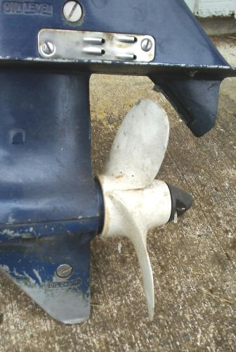 |
One other situation where this may be evident is if the shifting handle appears to be frozen. However remember the clutch slider has to be aligned with the gear recesses, so don't push the handle to much. If this is the case, pull the starter rope as you engage the shifting handle lever. This allows for any mismatch inside the gearbox and will allow the clutch dogs to engage the gears.
However before you tear everything down if the gearbox has any indication of having water in it an no rust yet, check the nylon oil drain and fill plugs as they are the first likely thing to cause leaks other than fish line around the prop shaft, ruining the rear seal.
This is not a unitized gearbox like most of the newer motors, and the bottom 1/2 comes off exposing the gears. To remove this lower 1/2 remove the (3) Allen head #2 screws on each side, then the (1) Allen head #1 shifting linkage pivot screw. The lower 1/2 can now be lifted off, possibly may need some persuasion however if someone gooped the 2 parts together.
Here, when you remove this bottom cover there will be a 3/16" X 3/4" stainless steel pivot pin in the shifting linkage yoke. Remove it before it falls out on it's own and lost.
| Here the gearbox is removed from the motor & the lower 1/2 also removed showing the gears & shaft bearings. Note the 3/16" hole in the shifting yoke. This is where the Allen headed PIVOT screw goes thru. |
|
|
If you suspect the rear seal (part # 49) leaking,
remove the bearing housing off the shaft and you will probably have to
make a slightly angled steel rod that you can go in from the front, thru
the bronze shaft bushing, engage
the front of the seal unit and drive it out the rear. New ones are available from about
any outboard marine dealer that can get BRP (old OMC) parts for under
$15.00. Oil Seal, OMC #313282 or Sierra / NAPA #18-2023. If that is not
readily available then take the old seal and shaft to a automotive parts store and let them measure /cross
reference it to a automotive seal that will function. You can use a
thinner seal but not a thicker than original one, just position it in
the housing so the rear of the seal is in the same location front to
rearward.
To install the new seal, be sure the hole in the bearing housing
is clean, lay the housing endways (front down), align the new seal,
start it by hand if possible. Then lay a flat piece of steel on
the seal, tap it in with a hammer. This way it can only go in as
far as the housing allows as the flat steel will stop because it is
hitting the housing.
When you reassemble the shaft and shifting slider dog, be sure that the slider yoke is positioned as shown above. Also the bearing housing has a hole that engages a peg in the upper housing that secures it and keeps it from rotating, be sure that is in the right place before you tighten down the cover.
Shift Lever Stops : The positive click stops for the shifting lever is by a Ell shaped bent spring that snaps into notches on the shifting rod inside the lower unit. This spring and a helper spring are screwed into the lower unit above the prop shaft which the spring detent mate into notches in the shifting rod. This motor's stops were non-functioning. However what I found was that the spring and helper were there and in fine shape, just that they had gotten slid forward enough to not engage into the rod's notches. So it was just a simple matter of realigning them then retightening the screw once the gearbox was apart.
In the photo below, with the bottom section of the gearbox removed, (photo looking UP) you will note the shifting rod is arced around the LH side of the gear unit and in the 2nd photo below see the cotter pin which attaches it to the shifting yoke. Notice when tightening the spring, the torque of tightening the screw rotates the spring, as seen below where this spring is slightly misaligned, this needs to be straightened before reassembly.
| The red arrow pointing to the area of the notches on the rod where the flat spring engages to secure it when in the selected gear |
|
|
Worn Clutch Gog Slider : If
the clutch dog slider (#37 in the
exploded view below, left) has become worn, this can also cause the motor to
jump out of forward gear, which gets worse as the load in the boat increases.
If this is the case, new ones are impossible to find and good used ones
are getting scarce. Some will tell you to reverse (flop ends) the sliding
clutch dog unit. Sorry, but this will not really work, well maybe for a while if it is not
really worn, because the drive side of this dog for forward will also be the
same side as when you flop it where you will then be using the same edge for
reverse. Worn is bad in either case.
I happen to be a retired machinist and still have a fairly
complete machine shop. For the well worn clutch dog shown below, I welded up the leading
edges of the dogs with a E9018 electric electrode rod, then ground them close by hand, doing the final fitting with
a Dremel tool and 1/8" carbide cutter.
Then I re-heat treated it by heating the whole end lug part to a dull red,
quenching in transformer oil and the drawing that end back by first polishing
it, then drawing that end back until the color just turns light blueish/purple.
Then let it air cool.
For the forward gear, which was worn just as bad, I mounted this gear in my milling machine and using a 3/8" carbide end mill, then recut the bad corner back about .040". Then did the same for the opposite side and by measuring the first as close as possible and trying to match it on the second. The reverse gear was treated the same. There is a lot of clearance/slop here for the clutch dog slider to move into, and this extra .040" would not make any appreciable difference.
If you are handy with a Dremel tool and using an 1/8" or 1/4" round Carbide cutter, you can do basically what I did mentioned above and just move the clutch dogs leading edge back so they are as close to the same dimensions as possible.
| Here is the worn clutch dog as seen on the top RH & bottom LH edges | Here the worn areas have been welded & hand ground to match close to the original shape | Here you can see the bright machined area on the RH edge (drive edge) of the forward gear |
|
|
|
|
There is a small magnet inserted in the upper rear of
the lower unit near where the rear propshaft bearing/seal housing nestles.
There is also a ear on the bearing housing that prevents it from rotating that
slides into a recess near that magnet.
This gearcase does not use a regular gasket, but a spaghetti rubber seal is .100" dia. allowing the two metals to mate tightly. This seal is purchased in bulk so you cut off just a bit more than you need. For this model 11" is enough. This seal is the same as used on all the other models that have the split gearbox, it may just be a different length depending on the size of the motor. It alone should do the job alone BUT if you were use a gasket sealant along with the seal that would only help. The main thing is that you want to keep it watertight. Also when you lay out the rubber seal in the groove, cut off just a little longer than needed as it will spread out in groove when housing is pressed together.
As said above it should not need any sealant, but many mechanics do so just as a precaution against gear oil leakage. This is not the only place where oil can leak.
Refill Gearbox Oil : OK, it's time to refill the gearbox with oil. The factory service manual for these motors recommends OMC Type C gear oil. It might be hard to find that anymore as all the newer oils being out there. Many say to use a synthetic gear oil, and that works fine, but if you go to your automotive parts store and just go home with a 80/90 weight gear oil, like used in rear ends of older cars or gearboxes on garden tractors/ lawn mowers, it will work just fine, and probably very close (or better) to the original OMC oil.
| Here the gearbox is being refilled with gear oil |
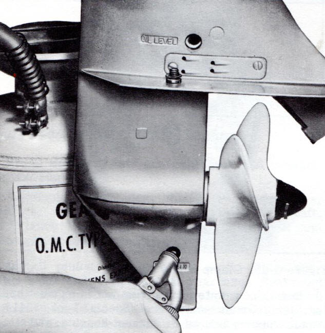 |
| Here is what a boater does not really want to see |
|
|
Prop : The prop uses a shear pin 3/16" (.187") diameter X 1.380" overall length. These pins appear to pretty substantial and I doubt if they would break before a blade on the prop. This motor that I am working on uses a 3 blade plastic prop #386587 in 8 1/2" X 5 size and has a 9/16" prop shaft hole. It's primary application is for sailboats and workboats. This prop on this one is a sort of metal filled plastic and must have been abused as it is now only 7" in dia. They are hard to find, but I lucked out finding a decent used one while snooping through a prop rack in a old outboard motor repair shop. The parts listing does not show the 3 blade prop even as an assessory. And Michigan Wheel does not list a cross-reference. My motor came with a 3 blade so I have not had the chance to compare it with a 2 blade for performance.
The 2 blade is aluminum 8" X 7 1/4 and the # is 0763745 which is the one usually found, and is still available.
The earlier 5 hp motors used a 1/2" prop shaft, then the 5.5hp and 6hp motors used the same size prop shaft, but once the hp of this series of motors gets to 7 1/2 hp, the prop shaft increases in size to 5/8" so any interchange of used props over that is not possible
If you are trying to replace a prop on these series, many eBay sellers do not know the differences, so you will have to educate them. Up through 1965, they used a drive pin through the aft end of the hub, using a brass nut and with a rubber cap. 1966 and later had the drive pin forward of the hub, with a threaded plastic cap nut. In addition, 1965 - back did not have a rubber hub, but a shock absorber in the gearcase, 1966-up had the rubber shock hub in the prop.
Prop Nut : For the 1966 and newer motors, the prop nut #0305394 is still available at a price of $16. The size of the prop nut threads are regular ½” SAE, or National FINE. You could use just a regular nut and drill 1/8” hole in it for the cotter pin. You will also need to use a flat washer between this nut and the rear of the prop. So with the prop slid on the shaft, slide the washer on the shaft behind the prop. Then you will have to measure/figure out the placement of the hole so that there is minimal forward/rearward play when installed and the retainer cotter pin is in place, or add more washers.
This particular motor also had a broken tiller handle and after searching e-Bay for a while I acquired a replacement off a later year, hence the different color on the photo below.
| 1972 Motor in running condition | |
|
|
copyright © 2009 - 2025 LeeRoy Wisner All Rights
Reserved
Back to the Ramblings
Home Page
Originally stated 06-03-2009, Last Updated 12-13-25
3-2025
Contact the author